Operating Manual Bellows pump series MP®-F Version MP-F05, MP-F05/R, MP-F10, MP-F10/R Gas sampling and gas conditioning technology 10.
List of content 1 2 3 4 5 6 7 8 General information .......................................................................................................................4 Declaration of conformity .............................................................................................................4 Safety instructions .........................................................................................................................5 Warranty .................................................
Dear customer, we have made up this operating manual in such a way that all necessary information about the product can be found and understood quickly and easily. Should you still have any question, please do not hesitate to contact M&C directly or go through your appointed dealer. Respective contact addresses are to be found in the annexe to this operating manual. Please also contact our homepage www.mc-techgroup.com for further information about our products.
Head Office M&C TechGroup Germany GmbH Rehhecke 79 40885 Ratingen Germany Telephone: 02102 / 935 - 0 Fax: 02102 / 935 - 111 E - mail: info@mc-techgroup.com www.mc-techgroup.com 1 GENERAL INFORMATION The product described in this operating manual has been examined before delivery and left our works in perfect condition related to safety regulations. In order to keep this condition and to guarantee a safe operation, it is important to heed the notes and prescriptions made in this operating manual.
3 SAFETY INSTRUCTIONS Please take care of the following basic safety procedures when mounting, starting up or operating this equipment: Read this operating manual before starting up and use of the equipment. The information and warnings given in this operating manual must be heeded. Any work on electrical equipment is only to be carried out by trained specialists as per the regulations currently in force.
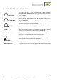
5 USED TERMS AND SIGNAL INDICATIONS DANGER! This means that death, severe physical injuries and/or important material damages will occur in case the respective safety measures are not fulfilled. WARNING! This means that death, severe physical injuries and/or important material damages may occur in case the respective safety measures are not fulfilled. This means that minor physical injuries may occur in case the respective safety measures are not fulfilled.
6 INTRODUCTION The bellows pumps MP-F are suitable for 100% oil free gas delivery of corrosive gases. They are designed especially in construction and performance for problems in the analysis technique. The pumps are gas tight and work maintenance free. 7 DESCRIPTION All sample contacting parts of the bellows pump MP-F are corrosion resistant. As option for piping the upper pump head part is available in stainless steel. The pump works absolutely lubricant free, so gases remain analytically unchanged.
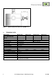
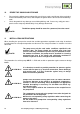
Figure 1 9 Bellows pump with needle valve type MP-F../R TECHNICAL DATA Bellows pump Part no. Part no. with needle valve MP-F../R Voltage MP-F05 /230V 05 P 1000 MP-F05 /115V 05 P 1000A MP-F10 /230V 05 P 1005 MP-F10/115V 02 P 1005A 05 P 1010 05 P 1010A 05 P 1015 05 P 1015A 230V 50Hz +/-5% 115V 60Hz +/-5% 230V 50Hz.+/-5% 115V 60Hz +/-5% Capacity max.
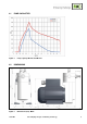
.1 PUMP CAPACITIES Figure 2 9.2 Pump capacity MP-F05 and MP-F10 DIMENSIONS Figure 3 10.1a-ME Dimensions (mm) MP-F..
RECEIPT OF GOODS AND STORAGE Please take the bellows pump and possible special accessories carefully out of the packaging material immediately after arrival, and compare the goods with the items listed on the delivery note! Check the goods for any damage caused during delivery and, if necessary, notify your transport insurance company without delay of any damage discovered.
.1 AMBIENT CONDITIONS During operation the following ambient conditions must be complied with: • Ambient temperature range during operation: -20 °C to +40 °C. • The pumps have to be protected against water and dust influence. • During operation a sufficient cooling air supply must be provided. 11.2 PUMP MOUNTING Mounting dimensions are shown in Figure 3. For sufficient ventilation the pump has to be mounted with a distance of min. 25mm to the wall. min. distance 25mm Figure 4 Mounting of MP-F.
Flange screws Figure 5 11.4 Turning the pump head SUPPLY CONNECTIONS 11.4.1 ELECTRICAL CONNECTIONS When making the electrical installation the safety regulations must be observed. In particular make sure that the electricity supply is isolated before trying to connect the pump. DANGER! The bellows pumps MP F.. are not allowed to be operated in explosive environments! Incorrect voltage can destroy the device.
NOTE! For the erection of power installations with nominal voltages up to 1000V the requirements of VDE 0100 and relevant standards and regulations must be complied with! The current supply circuit of pump type MP-F... (230 V) has to be provided with a motor circuit braker 0,3A corresponding to the rated current (overcurrent protection). The current supply circuit of pump type MP-F... (115 V) has to be provided with a motor circuit braker 0,57A corresponding to the rated current (overcurrent protection).
11.4.2 PNEUMATIC CONNECTION 12 Remove protective plugs from the gas connection threads (thread size G1/4“). There is the possibility to screw in the tube connection fittings as well on top as on the side of the pump head. For this remove protective plugs from the gas connection threads on the side and screw in these on top of the pump head.
To prevent the maximum permissible operating pressure being exceeded, restriction or control of the air or gas flow should only be carried out in the suction line. If restriction or control of the air or gas flow is made on the pressure side ensure that the maximum permissible operating pressure is not exceeded. Diaphragm and valve plates are the only parts subject to wear. Wear is usually indicated by a drastic reduction in the pneumatic performance.
14.1 EXCHANGE OF THE VALVE PLATES For the exchange of the valve plates the sample gas fittings does not have to be dismounted. Loosen the 4 hexagon socket screws G (key 3mm) and remove pressure ring H. Remove upper pump head A. O-rings C and valve plates B are freely accessible now. The valve plates and o-rings now can be cleaned or exchanged. Clean valve seat and pump head with an adequate solvent (e.g. alcohol) and blow out with compressed air.
15 TROUBLE SHOOTING Before working on the pump isolate the power supply securely, then check that the lines are not live.
16 SPARE PARTS LIST Wear, tear and replacement part requirements depend on specific operating conditions. The recommended quantities are based on experience and they are not binding. Bellows pump MP-F05, MP-F10, MP-F05/R, MP-F10/R (C) Consumable parts (R) Recommended spare parts (S) Spare parts Part No.