
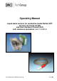
Operator's manual Owner's manual

3
Gas sampling and conditioning technology 5-5.1.1-ME
Contents
1 General information .................................................................................................................... 4
2 Declaration of conformity ........................................................................................................... 4
3 Safety instructions ...................................................................................................................... 5
4 Warranty ....................................................................................................................................... 5
5 Used terms and signal indications ............................................................................................ 6
6 Introduction .................................................................................................................................. 6
7 Application ................................................................................................................................... 7
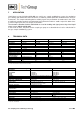
8 Technical Data ............................................................................................................................. 7
9 Description ................................................................................................................................... 8
10 Receipt of goods and storage .................................................................................................... 8
11 Installation instructions and Dimensions ................................................................................ 9
12 Mounting .................................................................................................................................... 11
12.1 Pre-assembly at works in case of complete control units .................................................. 11
12.2 Mounting of the sensor LA 1S into the universal filter ........................................................ 12
12.3 Mounting of the sensor LA 1S into the flow chamber LS .................................................... 12
12.4 Mounting of the Sensor LA 25S onto the Universal filter .................................................... 13
12.5 Mountage of the Sensor LA 25S into the flow chamber LS 25 ........................................... 13
13 Supply connections .................................................................................................................. 14
13.1 Electrical connections ......................................................................................................... 14
13.1.1 Electronic controller LA-1.1 ....................................................................................... 14
13.1.2 Electronic controller LA-1.4 ....................................................................................... 16
13.2 Pneumatical connections ................................................................................................... 17
14 Starting ....................................................................................................................................... 17
14.1 Starting with a dry sensor ................................................................................................... 17
14.2 Function test ....................................................................................................................... 18
14.3 Adjustment of sensitivity ..................................................................................................... 18
14.4 Adjustment of alarm holding function ................................................................................. 19
15 Closing down ............................................................................................................................. 19
16 Maintenance and repair ............................................................................................................ 20
17 Spare parts list ........................................................................................................................... 21
18 Appendix .................................................................................................................................... 21
List of illustrations
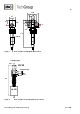
Figure 1 Flow chamber LS with liquid sensor LA 1S .................................................................... 10
Figure 2 Flow chamber LS 25 with liquid sensor LA 25S ............................................................. 10
Figure 3 Liquid alarm sensor LA 1S and LA 25S with universal filter F..-..D and FSS-..-D .......... 11
Figure 4 Mounting of the sensor LA 1S into flow chamber LS ...................................................... 13
Figure 5 Electrical connection and dimensions LA-1.1 ................................................................. 15
Figure 6 Electrical connection and dimensions LA-1.4 ................................................................. 16
Figure 7 Insertion plan of the LA-1.4 ............................................................................................ 17
Figure 8 Flow diagram LA1.1, 115/230V 50/60Hz ........................................................................ 22
Figure 9 Flow diagram LA1.1, 24V AC/DC ................................................................................... 23
Figure 10 Flow diagram LA1.4, 115/230V 50/60Hz ........................................................................ 24
Figure 11 Flow diagram LA1.4, 24V AC/DC ................................................................................... 25