
Operator's manual Owner's manual

16
Gas sampling and conditioning technology 5-5.1.1-ME
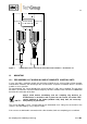
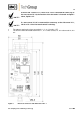
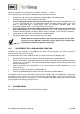
13.1.2 ELECTRONIC CONTROLLER LA-1.4
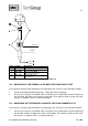
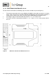
For the electrical connection, the following steps have to be carried out (see also figure 5):
The electrical connection of the sensor LA 1S or LA 25S is to be made on terminals 5 = brown
and 6 = white. Old sensors of type LA 1, LA 25 and LA 1-H are to be connected to terminals 5
= brown and 8 = white. In this case, you must install a bridge between terminals 6 and 7.
The voltage supply is to be effected on the terminals 1 = L, 2 = N and 4 = PE.
The alarms are to be connected on terminals 11, 21 = alarm, 12, 22 = centre contact and 14,
24 = o.k..
Figure 6 Electrical connection and dimensions LA-1.4