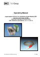
Operating Manual Liquid alarm sensors for conductive media Series Version LA 1S and LA 25S and flow chambers LS and LS 25 with electronic controllers LA 1.1, LA 1.4 Gas sampling and conditioning technology LA® 5-5.1.
Dear customer, we have made up this operating manual in such a way that all necessary information about the product can be found and understood quickly and easily. Should you still have any question, please do not hesitate to contact M&C directly or go through your appointed dealer. Respective contact addresses are to be found in the annexe to this operating manual. Please also contact our homepage www.mc-techgroup.com for further information about our products.
Contents 1 General information .................................................................................................................... 4 2 Declaration of conformity ........................................................................................................... 4 3 Safety instructions ...................................................................................................................... 5 4 Warranty ...................................................................
Head Office M&C TechGroup Germany GmbH Rehhecke 79 40885 Ratingen Germany Telephone: 02102 / 935 - 0 Fax: 02102 / 935 - 111 E - mail: info@mc-techgroup.com www.mc-techgroup.com 1 GENERAL INFORMATION The product described in this operating manual has been examined before delivery and left our works in perfect condition related to safety regulations. In order to keep this condition and to guarantee a safe operation, it is important to heed the notes and prescriptions made in this operating manual.
3 SAFETY INSTRUCTIONS Please take care of the following basic safety procedures when mounting, starting up or operating this equipment: Read this operating manual before starting up and use of the equipment. The information and warnings given in this operating manual must be heeded. Any work on electrical equipment is only to be carried out by trained specialists as per the regulations currently in force.
5 USED TERMS AND SIGNAL INDICATIONS DANGER! This means that death, severe physical injuries and/or important material damages will occur in case the respective safety measures are not fulfilled. WARNING! This means that death, severe physical injuries and/or important material damages may occur in case the respective safety measures are not fulfilled. This means that minor physical injuries may occur in case the respective safety measures are not fulfilled.
7 APPLICATION Liquid alarm sensors LA 1S and LA 25S are used in gas sample conditioning systems for monitoring gas cooling and condensate drain-off devices in order to provide protection for downstream analysis instruments. This simple monitoring device reliably signals the penetration of condensate in the event of cooling or condensate drain-off equipment being defective and thus avoids expensive down times as well as high repair costs for analysis instruments. The electronic controllers LA-1.
9 DESCRIPTION The M&C liquid sensors LA..S works on the principle of electrical conductivity from 20 µS/cm conductance. In order to avoid electrolytic effects on the sensor surface, the sensors are powered with alternating current. NOTE! Only the newly developed electronic controllers as described in the afore mentioned data sheet from date of construction 04/2006 onwards can be used for the M&C liquid sensors LA..S. The M&C LA..
NOTE! 11 The liquid alarm components should be stored in a protected frost-free area ! INSTALLATION INSTRUCTIONS AND DIMENSIONS The liquid alarm sensor LA ..S is used for detecting liquids and is to be installed behind the gas dehydration devices, e.g. behind a gas cooler, but always on the deepest point of the installation. This is provided by the universal filters F.-..-D and the flow chambers LS or LS 25. The filters F.-..
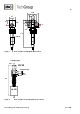
17 25 ø50 12 G1/4" 13 25 LS LS 12 G1/4" ø5 115 LA LA11S Figure 1 Flow chamber LS with liquid sensor LA 1S Sample gas DN 8 LS 25 Sample gas DN 8 120 LA 25S Figure 2 Flow chamber LS 25 with liquid sensor LA 25S Gas sampling and conditioning technology 5-5.1.
Sample gas Universal filter Sample gas F..-..D / FSS-..-D 290 290 LA 25S LA 1S Figure 3 Liquid alarm sensor LA 1S and LA 25S with universal filter F..-..D and FSS-..-D 12 MOUNTING 12.1 PRE-ASSEMBLY AT WORKS IN CASE OF COMPLETE CONTROL UNITS In case you order a complete control unit consisting of liquid sensor, universal filter or flow chamber and electronic controller, the mounting of the sensor into the respective installation device is effected at works as far as possible.
12.2 MOUNTING OF THE SENSOR LA 1S INTO THE UNIVERSAL FILTER In case the client has selected single components, the mounting of the sensor has to be effected as follows: Dismount the red GL25 union nut incl. the inside GL25-12 clamping ring from the filter. Tear the red anti-kink socket of the cable on the sensor LA 1S by slight swinging movements backwards in direction of the connection cable of the sensor body.
Union nut Antikink Item 1 2 3 Part-No. 90 E 1000 90 E 1010 03 E 1001 4 03 E 3100 Description FPM O-ring 14 PVDF – pressing ring 16 Liquid sensor LA 1S with 4m connection cable Flow chamber LS with union nut Figure 4 12.
13 SUPPLY CONNECTIONS 13.1 ELECTRICAL CONNECTIONS WARNING! NOTE! Incorrect supply voltage may destroy the equipment. Please take care of the correct voltage as indicated on the type plate! The supply voltage may vary from the indication on the type plate by max. ± 10%.
NOTE! NOTE! If the the old sensor LA 1, LA 25 or LA 1-H is connected the same way as the new sensor LA 1S, the function of the electronic is inverted: no liquid = alarm, liquid = o.K. If a new sensor LA 1S is connected the same way as the old sensor LA 1, LA 25 or LA 1-H no line break control is existing. The voltage supply takes place on terminals 1 = L, 2 = N and 3 = PE. The alarm is to be connected to terminals 11, 21 = centre contact, 12, 22 = alarm and 14, 24 = o.k..
13.1.2 ELECTRONIC CONTROLLER LA-1.4 For the electrical connection, the following steps have to be carried out (see also figure 5): The electrical connection of the sensor LA 1S or LA 25S is to be made on terminals 5 = brown and 6 = white. Old sensors of type LA 1, LA 25 and LA 1-H are to be connected to terminals 5 = brown and 8 = white. In this case, you must install a bridge between terminals 6 and 7. The voltage supply is to be effected on the terminals 1 = L, 2 = N and 4 = PE.
Figure 7 13.2 Insertion plan of the LA-1.4 PNEUMATICAL CONNECTIONS For the connection of the measuring gas lines and when using the universal filters F..-..-D and the flow chamber LS, you must use two fittings with thread G1/4“ a and the corresponding tube and pipe connection. The screw fittings have to be screwed into the universal filter respectively the flow chamber by using PTFE tape. The flow chamber LS 25 is already equipped with screw fittings for 8mm tubes.
In case the read alarm LED is beaming, there is liquid on the sensor, or there is a line break, or you must do an adjustment of the sensitivity (see chapter 14.3). NOTE! 14.2 If the sensor is dry, the green LED indicates that the instrument is in operating condition, the green LED is out when the red LED is on and signalizes a liquid alarm.
Range of adjustment on the electronic controllers: 50µS/cm … 1mS/cm. For an adjustment of sensitivity, the following steps have to be executed: Remove the 4 lid screws of the electronic controller LA-1.1 and remove the lid. Dismount the sensor, clean and dry the electrodes. In case of permanent alarm with a dry and clean sensor: Turn on the potentiometer P1 (LA1.1) resp. Sensitivity adj. (LA-1.4) anticlockwise (lower sensitivity) until the alarm is out.
16 MAINTENANCE AND REPAIR NOTE! Please take care of the specific installation and process safety measures before executing any maintenance and repair work! The liquid control units series LA® are working maintenance-free during a long period of time. It may be that the electrodes of the sensors LA 1S resp. LA 25S are dirty from deposits. Please use a cloth for cleaning, eventually in connection with a solvent of cleaning material. For cleaning, the sensor has to be dismounted.
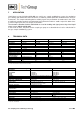
17 SPARE PARTS LIST The requirement of wear, tear and spare parts depend on specific operating conditions. The quantities we recommend are based on experience and are not binding. Liquid alarm sensor unit LA... (V) Consumables, (E) Recommended spare parts, (T) Spare parts Recommended quantity for operation during a period of xxx years V/E/T 1 2 3 Sensor LA 1S / LS: 90 E 1000 FPM O-Ring (14) E 2 4 8 90 E 1010 PVDF-Ring (16) E 2 4 8 Sensor LA 1S / F.-..
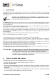
Figure 8 Flow diagram LA1.1, 115/230V 50/60Hz Gas sampling and conditioning technology 5-5.1.
Figure 9 Flow diagram LA1.1, 24V AC/DC Gas sampling and conditioning technology 5-5.1.
Figure 10 Flow diagram LA1.4, 115/230V 50/60Hz Gas sampling and conditioning technology 5-5.1.
Figure 11 Flow diagram LA1.4, 24V AC/DC Gas sampling and conditioning technology 5-5.1.