
Manual

M&C TechGroup Germany GmbH • Rehhecke 79 • 40885 Ratingen • Germany
info@mc-techgroup.com • www.mc-techgroup.com • Fon +49 2102 935-0 • Fax +49 2102 935-111
11.1
Technical specications and illustrations are without
obligation, subject to modications. 08.98/11.06
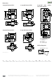
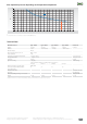
Dimensions
Abmessungen in mm
3-way-ball valve 3L/PV-12-way-ball valve 2L/PV-1
5-way-ball valve 5L/PV-14-way-ball valve 4L/PV-1
5-way-ball valve 5L/PV-1
with status contact
1. Central point/outlet
2. controlled connection,
i.e. sample gas
3. I.e. zero gas
4. I.e. calibration gas 1
5. I.e. calibration gas 2
Drilling diagramm
D G H H1 I L L1 L2 L3 s SW1 SW2 T w1 w2
ø 20 G1/4"i 41,5 12,5 46 65 15 75 57,5 max. 5 32 27 32 26 22
D
T
G
SW1 L1
H
S
H1
L3
I
L
W1
D
T G
L1
SW2
H
S
H1
L2
I
L
W2
G1/4"
64
3415
328
110
120
2
5
4
3
5
2
3
1
321
ø 5
31 2
ø 5
D
G
L1
SW1
H
S
H1
L3
I
L
W1
D
G
L1
SW2
H
S
H1
L2
I
L
W2
diameter 22
R0,75
45
*
plate thickness < 7 mm
* controlled position
drilling diagram