Operating Manual Liquid Alarm Sensor KS2 / KS2.Ex for non-conductive and conductive media Gas sampling and conditioning technology 5-5.
Dear customer, we have made up this operating manual in such a way that all necessary information about the product can be found and understood quickly and easily. Should you still have any question, please do not hesitate to contact M&C directly or go through your appointed dealer. Respective contact addresses are to be found in the annexe to this operating manual. Please also contact our homepage www.mc-techgroup.com for further information about our products.
Content 1 2 3 4 5 6 7 8 9 General information....................................................................................................................... 4 Declaration of conformity ............................................................................................................. 4 Safety instructions ........................................................................................................................ 5 Warranty ...................................................
Head Office M&C TechGroup Germany GmbH Rehhecke 79 40885 Ratingen Germany Telephone: 02102 / 935 - 0 Fax: 02102 / 935 - 111 E - mail: info@mc-techgroup.com www.mc-techgroup.com 1 GENERAL INFORMATION The product described in this operating manual has been examined before delivery and left our works in perfect condition related to safety regulations. In order to keep this condition and to guarantee a safe operation, it is important to heed the notes and prescriptions made in this operating manual.
3 SAFETY INSTRUCTIONS Please take care of the following basic safety procedures when mounting, starting up or operating this equipment: Read this operating manual before starting up and use of the equipment. The information and warnings given in this operating manual must be heeded. Any work on electrical equipment is only to be carried out by trained specialists as per the regulations currently in force.
5 USED TERMS AND SIGNAL INDICATIONS DANGER! This means that death, severe physical injuries and/or important material damages will occur in case the respective safety measures are not fulfilled. WARNING! This means that death, severe physical injuries and/or important material damages may occur in case the respective safety measures are not fulfilled. This means that minor physical injuries may occur in case the respective safety measures are not fulfilled.
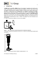
6 APPLICATION Liquid alarm sensors are used in gas sample conditioning systems for monitoring gas cooling and condensate removal devices in order to provide protection for downstream analysis instruments. This monitoring device KS2 / KS2.Ex reliably signals the penetration of non conductive (e.g. alcohol) and conductive (e.g. water) liquid in the event of cooling or condensate removal equipment being defective, thus avoiding expensive down time as well as high repair costs for analysis instruments.
7 TECHNICAL DATA Sensor Part No. Pressure Max. operating temperature Liquid alarm limit Material of sample contacting parts Sample connection Standard (Fitting for mounting in stainless steel filter: connector GE SS ½“NPT18mm Part No.. 09V2317) Option sample connection ø18 mm, Part No..: 03E9400 (Fitting for mounting in stainless steel filter: connector GE SS ½“NPT18mm Part No.. 09V2317) Method of mounting / mounting position Max. voltage / current / power consumption Inner capacity max.
8 DESCRIPTION The M&C liquid sensor KS2 / KS2.Ex works on the principle of capacitive measurement and is suitable for non-conductive and conductive media. A pre-amplifier is integrated in the sensor housing and is connected with the necessary external electronic controller via 2- resp. 3-wire. For the sensor type KS2 the required electronic controller is available in various versions, FA1.1 or FA1.4 and is described in a separate data sheet. The M&C liquid sensor KS2.
9 FUNCTION 9.1 CONNECTION AND ADJUSTMENT OF THE SENSOR TYPE KS2 AT THE ELECTRONIC FA1.1 Link the sensor to the electronic FA1.1 (see also manual 5-6.10ME) KS2 terminal X4/3 to FA1.1 terminal 15 (yellow) KS2 terminal X4/2 to FA1.1 terminal 17 (white) KS2 terminal X4/1 to FA1.1 terminal 18 (brown) Adjustment with „dry“ sensor: Turn the potentiometer to the left until the green LED is OFF and the red LED is ON. Turn the potentiometer very slowly to the right.
9.3 CONNECTION OF THE SENSOR TYPE KS2.EX TO THE ELECTRONICS WE77/EX1 NOTE! The bridge between the connecting points 3 and 4 of the electronics WE77/Ex1 guarantees a „safty-first“ alarm release (alarm in case of voltage loss and parting of the cable).
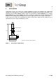
9.5 ADJUSTMENT OF THE SENSOR TYPE KS2.EX Electronics WE77/Ex1 Sensor Left Right Bridge Poti Figure 4 Electronic KFA6-SR2-Ex1.W (left) and terminal box KS2.Ex respectively WE77/Ex1 Turn the potentiometer (figure 4) to the left until the LED is OFF. Turn the potentiometer slowly to the right. After the LED is ON, turn the potentiometer for another 1,5 rotations to the right. Sensor KS2.
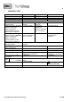
Technical data for switch amplifiers (techn. data sensor see page 5) Evaluation for example by section switch amplifier KFA6-SR2-Ex1.W Nominal revolutions according to DIN 19234 respectively Namur Voltage UO 10,6 V Current I0 19 mA Power consumption P0 51 mW Data according to certificate of conformity for KS2.Ex Voltage max. UO 13,5V Current max. IK 31mA Power consumption Pmax 125mW Permissible connection data EEx ia EEx ia Class IIB IIC Outer capacity max. 929nF 230nF Outer inductivity max.
11 SPARE PARTS LIST Wear, tear and replacement part requirements depend on specific operating conditions. The recommended quantities are based on experience and are not binding. Liquid sensor type KS2 / KS2.Ex (C) consumable parts and (R) recommended spare parts recommended quantity KS2/KS2.
O-Ring 9 Chemraz Art.-No.: 91E4005 O-Ring 9 Viton Art.-No.: 91E4010 O-Ring 15 Chemraz Art.-No.: 91E4000 Mutter GL 25/18 Art.-No.: 90F0022 O-Ring 13 Viton Art.-No.: 91E4015 Grub srew M3x10 Gasket Viton PG7 Circuit board with sensor Figure 6 Mounting of the sensor type KS2 Gas sampling and conditioning technology 5-5.
Gas sampling and conditioning technology 5-5.
Gas sampling and conditioning technology 5-5.