OPERATING INSTRUCTIONS Flowmeter Series FM® Version FM-2K, FM-200K-H, FM-200K-H/FA Gas sampling and gas conditioning technology 5-6.5.
Dear customer, we have made up this operating manual in such a way that all necessary information about the product can be found and understood quickly and easily. Should you still have any question, please do not hesitate to contact M&C directly or go through your appointed dealer. Respective contact addresses are to be found in the annexe to this operating manual. Please also contact our homepage www.mc-techgroup.com for further information about our products.
Contents 1 2 3 4 5 6 7 8 9 10 11 12 13 14 15 16 17 18 19 20 General information...................................................................................................................... 4 Declaration of conformity ............................................................................................................ 4 Safety instructions ....................................................................................................................... 5 Warranty ....................
Head Office M&C TechGroup Germany GmbH Rehhecke 79 40885 Ratingen Germany Telephone: 02102 / 935 - 0 Fax: 02102 / 935 - 111 E - mail: info@mc-techgroup.com www.mc-techgroup.com 1 GENERAL INFORMATION The product described in this operating manual has been examined before delivery and left our works in perfect condition related to safety regulations.
3 SAFETY INSTRUCTIONS Please take care of the following basic safety procedures when mounting, starting up or operating this equipment: Read this operating manual before starting up and use of the equipment. The information and warnings given in this operating manual must be heeded. Any work on electrical equipment is only to be carried out by trained specialists as per the regulations currently in force.
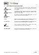
5 USED TERMS AND SIGNAL INDICATIONS DANGER! This means that death, severe physical injuries and/or important material damages will occur in case the respective safety measures are not fulfilled. WARNING! This means that death, severe physical injuries and/or important material damages may occur in case the respective safety measures are not fulfilled. This means that minor physical injuries may occur in case the respective safety measures are not fulfilled.
6 INTRODUCTION Flowmeters are used in analysis technique to control the gas flow. In dependance of the application it could be necessary to use a heated or heatable version. Especially for this applications the M&C flowmeters FM-2K and FM-200K-H(/FA) are designed. 7 SERIAL NUMBERS The nameplates bearing the serial number are located on the mounting plate. NOTE! 8 Always quote the device's serial number when making enquiries and ordering replacement parts.
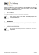
10 TECHNICAL DATA Technical Data Part-No. Heated / needle valve in the inlet Optical flow control, mono-stable ** Standard measuring range Measuring ranges available FM-2K 09F2105 no FM-200K-H 09F2505 yes FM-200K-H/FA 09F2555 ** yes no no fix between 20 - 50% of scale 25-250 l/hr air, 1.2 bar, 180°C Scale: 1.6-16, 6-60, 10-100, 1.2 bar, 180°C max.
11 APPLICATIONS The M&C flowmeters FM-2K and FM-200K-H(/FA) are used in analysis technique to control gas flow up to an operating temperature of 180 °C. Depending on the flowmeter glass tube, ranges from 16 l/h to 800 l/h can be realized. 12 DESCRIPTION The M&C flowmeters FM-2K and FM-200K-H(/FA) consist of a vertical cone shaped glass tube with a free movable float ball inside.
13 DELIVERY ® The flowmeter Series FM is normally delivered in one packaging unit: ® The flowmeter Series FM should be removed carefully from the packaging and checked immediately for completeness against the delivery note. Check the goods for any damage incurred during transport and if necessary inform your transport insurer of any damage. 14 PREPARATION AND INSTALLATION ® Locate the flowmeter Series FM in such a way that there is adequate space for removing the cover and replacing the glass tube.
16 ELECTRICAL CONNECTION WARNING! NOTE! When connecting the equipment, please ensure that the supply voltage is identical with the information provided on the model type plate. Attention must be paid to the requirements of IEC 364 (DIN VDE 0100) when setting high-power electrical units with nominal voltages of up to 1000 V, together with the associated standards and stipulations.
Figure 2 17 Electrical connections for FM-200K-H(/FA) STARTING Before starting up check whether the mains power supply voltage corresponds with the information stated on the type plate. Switch on mains power supply. The total heating-up time is approximately 30 min. The flowmeter then is ready for operation Gas sampling and gas conditioning technology 5-6.5.
18 MAINTENANCE The safety instructions specific to the plant and process are to be consulted prior to any maintenance work! NOTE! It is difficult to give any recommendations as to a particular maintenance cycle. Depending on your process conditions, a meaningful maintenance cycle must be elaborated for the specific application. Check from time to time, if the flowmeter glass is soiled. Aggressive condensate is .
19 SPARE PARTS LIST Wear, tear and replacement part requirements depend on specific operating conditions. The recommended quantities are based on experience and they are not binding. ® Flowmeter Series FM ((C) Consumable parts (R) Recommended spare parts (S) Spare parts Part No. 91 F 1040 90 S 2042 91 F 2000 91 F 2000a 90 P 5020 20 Indication Spare o-ring set for flowmeter FM..-HT 2 pcs. PTFE spiral o-rings type MAA 612-01-05-1 O-ring (11) for and FM-2K, FM-200K/H Material: Viton.
Figure 3 Electrically heated flowmeter FM-200H/FA incl. monostable flow alarm Gas sampling and gas conditioning technology 5-6.5.
Figure 4 Electrically heated flowmeter FM-200H Gas sampling and gas conditioning technology 5-6.5.