
Operator's manual User Manual

12
Gas sampling and gas conditioning technology 5-6.15ME
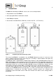
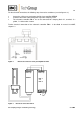
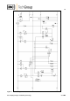
For the electrical connection, the following steps have to be carried out (see also figure 2+3):
Loosen the 4 lid screws and remove the lid of pre-amplifier K-FA-H.
Lead the connection cable through the respective clamping screw.
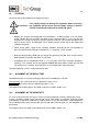
The electronic controller FA-1.. has to be connected on clamping block X1, terminals 5 =
yellow, 7 = white and 8 = brown.
Further electrical connection of the electronic controller FA-1.. is described in manual 5-6.10ME,
chapter 13.
Figure 2 Electrical connection of the pre-amplifier K-FA-H
Figure 3 Electrical connection FA1-H
8
7
6
5
18
17
16
15
1
2
3
14
11
12
L
N
P
E
br
ws
ge
br
ws
ge
FA-K-H
FA1.1
and
FA1.4
NC