Operating Manual Optical flow alarm FA1-H Gas sampling and gas conditioning technology 5-6.
List of Contents 1 2 3 4 5 6 7 8 General information .................................................................................................................. 4 Declaration of conformity ........................................................................................................ 4 Safety instructions .................................................................................................................... 5 Warranty .........................................................
Dear customer, we have made up this operating manual in such a way that all necessary information about the product can be found and understood quickly and easily. Should you still have any question, please do not hesitate to contact M&C directly or go through your appointed dealer. Respective contact addresses are to be found in the annexe to this operating manual. Please also contact our homepage www.mc-techgroup.com for further information about our products.
Head Office M&C TechGroup Germany GmbH Rehhecke 79 40885 Ratingen Germany Telephone: 02102 / 935 - 0 Fax: 02102 / 935 - 111 E - mail: info@mc-techgroup.com www.mc-techgroup.com 1 GENERAL INFORMATION The product described in this operating manual has been examined before delivery and left our works in perfect condition related to safety regulations.
3 SAFETY INSTRUCTIONS Please take care of the following basic safety procedures when mounting, starting up or operating this equipment: Read this operating manual before starting up and use of the equipment. The information and warnings given in this operating manual must be heeded. Any work on electrical equipment is only to be carried out by trained specialists as per the regulations currently in force.
5 USED TERMS AND SIGNAL INDICATIONS This means that death, severe physical injuries and/or important material damages will occur in case the respective safety measures are not fulfilled. DANGER! WARNING! This means that death, severe physical injuries and/or important material damages may occur in case the respective safety measures are not fulfilled. This means that minor physical injuries may occur in case the respective safety measures are not fulfilled.
6 INTRODUCTION Optical flow monitoring systems are used for contiuous gas analysis with corrosive sample gases, to have the possibility of using flowmeters with corrosion resistant floating balls out of e.g. glass. The optical flow monitoring systems FA1-H-.. are an alternative to the optical flow monitoring systems FA-1 with light fork barrier. These units can be used in heated gas conditioning systems up to 180°C also with non metallic or very small floating balls.
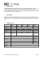
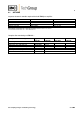
8.1 OPTIONS Separate electronic controller required for the K-FA-H pre-amplifier: Electronic controller Part No. 230V 50/60Hz Part No. 115V 50/60Hz Part No. 24V DC Part No. 24V AC FA-1.1 02 E 7300* 02 E 7300* 02 E 7300 d 02 E 7300 b FA-1.4 02 E 7110 02 E 7110 a 02 E 7110 d 02 E 7110 d Complete flow monitoring unit FA1-H-..
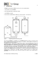
9 DESCRIPTION The M&C flow monitoring unit FA1-H-.. consists of 4 sub-assembly modules: 1. the patented sensor head FA2-H, 2. the 2 light guides FO.. for monostable function 3. the K-FA-H pre-amplifier 4. the electronic controller FA-1.1 or FA-1.4 (see data sheet FA-.., K-FA 5-6.10.2) Figure 1 Complete optical flow monitoring system The sensor head FA2-H is assembled on e.g. the FM1-H flowmeter by means of a pressure screw with its stationary open prism to the measuring glass.
10 RECEIPT OF MARCHENDISE AND STORAGE The optical flow monitoring system is delivered in 4 sub-assembly modules : sensor head FA2-H, 2 light guides FO.. K-FA-H pre-amplifier electronic controller FA-1.1 or FA-1.4.
First of all, the 2 light guide ends have to be mounted according to their marking (1+2). They are mounted with their metal screwing ends in the connection adapter OA-bi which is situated in the housing wall of the pre-amplifier K-FA-H for mounting in "cold area" by turning right-hand until limit stop. Push one angled light guide end according to the marking (2) into the location hole on the left side of the sensor head FA2-H. Push them as far as they touch the measuring glass of the flowmeter e.
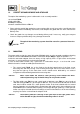
For the electrical connection, the following steps have to be carried out (see also figure 2+3): Loosen the 4 lid screws and remove the lid of pre-amplifier K-FA-H. Lead the connection cable through the respective clamping screw. The electronic controller FA-1.. has to be connected on clamping block X1, terminals 5 = yellow, 7 = white and 8 = brown. Further electrical connection of the electronic controller FA-1.. is described in manual 5-6.10ME, chapter 13.
13 STARTING Check the correct constellation of the equipment (Fig.1). False supply voltage can damage the equipment. When connecting W A R N I N G ! the equipment, please ensure that the supply voltage is identical with the information provided on the model type plate! Without gas charging, the floating ball in the flowmeter is in down position.
14 MAINTENANCE NOTE! Before carrying out any maintenance or repair work, the specific safety procedures pertaining to the system and the operational process have to be observed! The flow control units series FA® are functioning without necessity of maintenance over a long time. It may be that the LED and the phototransistors of the flow alarm sensor FA-2H must be cleaned due to dust deposits. Please execute this cleaning with a dry cotton bud (Q-tip).
Figure 4 Circuit diagram of electronic K-FA-H 115/230V Gas sampling and gas conditioning technology 5-6.