
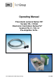
Operator's manual Owner manual

3
Gas sampling and conditioning technology 5-6.10-ME
Contents
1 General information ................................................................................................................... 4
2 Declaration of conformity ......................................................................................................... 4
3 Safety instructions ..................................................................................................................... 5
4 Warranty ..................................................................................................................................... 5
5 Used terms and signal indications ........................................................................................... 6
6 Introduction ................................................................................................................................ 7
6.1 Patented flow alarm sensor .................................................................................................. 7
7 Application ................................................................................................................................. 7
8 Technical data ............................................................................................................................ 8
9 Description ................................................................................................................................. 9
10 Receipt of goods and storage ................................................................................................ 10
11 Installation instructions .......................................................................................................... 10
12 Mounting ................................................................................................................................... 11
13 Electrical connection ............................................................................................................... 11
13.1 Electronic controller FA-1.1 ................................................................................................ 12
13.2 Electronic controller FA-1.4 ................................................................................................ 13
13.3 Pre-amplifier K-FA ............................................................................................................. 14
14 Starting ..................................................................................................................................... 15
14.1 Sensitivity Adjustment for electronic controllers FA1.1 and FA1.4 ..................................... 16
14.2 Sensitivity adjustment for use of pre-amplifier K-FA.. ......................................................... 16
14.3 Adjustment of the delay time .............................................................................................. 17
15 Closing down ........................................................................................................................... 18
16 Maintenance and Repair .......................................................................................................... 18
17 List of spare parts .................................................................................................................... 18
18 Annexe ...................................................................................................................................... 19
List of illustrations
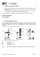
Figure 1 Flow alarm sensor FA-1/2/3bi on measuring glass with bi-stable or mono-stable
function ................................................................................................................................. 10
Figure 2 Electrical connection and dimensions FA-1.1....................................................................... 12
Figure 3 Electrical connection and dimensions FA-1.4....................................................................... 13
Figure 4 Assembly plan of the FA-1.4 ................................................................................................ 14
Figure 5 Electrical connection K-FA ................................................................................................... 15
Figure 6 Circuit diagram of the electronic controller FA1.1, 115/230V ............................................... 20
Figure 7 Circuit diagram of the electronic controller FA1.1, 24VAC ................................................... 21
Figure 8 Circuit diagram of the electronic controller FA1.4, 115/230V ............................................... 22
Figure 9 Circuit diagram of the electronic controller FA1.4, 24V AC/DC ............................................ 23
Figure 10 Circuit diagram of the electronic controller K-FA (-H), 115/230V ......................................... 24