
Operator's manual Owner manual
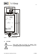

17
Gas sampling and conditioning technology 5-6.10-ME
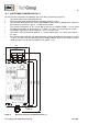
Adjust the voltage signal on the electronic board of the pre-amplifier K-FA.. for both photo
transistors to a value between +0,08 (lowest sensitivity) to + 0,18 VDC (highest sensitivity). The
tension is to be measured on the connection points of the sensor’s connection cables or the
soldering points M1 – M3. The adjustment is to be made on the potentiometers P1 and P2.
NOTE!
When adjusting the sensitivity, the following principle should be considered:
As sensitive as necessary, as insensitive as possible.
ws (white) resp. M2 = lower phototransistor, adjustable at P1
gn (green) resp. M1 = upper phototransistor, adjustable at P2
ge (yellow) resp. M3 = earth
Measurement to be made in bi-stable version between:
ge (yellow) resp. M3 = 0V and ws (white) resp. M2 = +V (lower phototransistor)
ge (gelb) resp. M3 = 0V and gn (green) resp. M1 = +V (upper photoransistor)
Measurement to be made in mono-stable version between:
ge (yellow) resp. M3 = 0V and ws (white) resp. M2 = +V (only lower phototransistor)
14.3 ADJUSTMENT OF THE DELAY TIME
By applying the following, unwanted alarm indication in case of pulsating gas flow can be avoided.
Slow operation: Alarm release is given with a time-lag.
Slow release: Alarm is given with a time-lag.
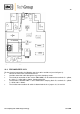
The electronic board is accessible as follows:
In wall mounting version FA-1.1 by removing the 4 lid screws.
In the rail mounting version FA-1.4 you have to loosen the locking behind the terminals on the
upper and lower side by using a screw driver. Then, you can tear the printed board together
with the housing front out of the back housing part.
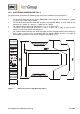
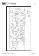
The pick-up and drop-out time delay of the alarm relay is adjustable with the fixed resistors R16/R17 at
the adjusting points on the electronic board of the electronic controller FA-1.. .
The position of the resistors is to be seen in figures 2 and 4.
Resistor
Slow operation
Resistor
Slow release
R17 1 KΩ
approx. 0 seconds
R16 1 KΩ
approx. 0 seconds
R17 100 KΩ*
approx. 3 seconds
R16 100 KΩ*
approx. 2 seconds
R17 270 KΩ
approx. 7 seconds
R16 270 KΩ
approx. 6 seconds
R17 560 KΩ
approx. 11 seconds
R16 560 KΩ
approx. 10 seconds
R17 1 MΩ
approx. 14 seconds
R16 1 MΩ
approx. 13 seconds
* Standard adjustment at works = 33 KΩ = 1second pick-up and drop-out time delay
The times represent approximate values and are dependent on the tolerances of the components.