
Operator's manual Owner manual

14
Gas sampling and conditioning technology 5-6.10-ME
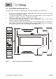
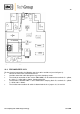
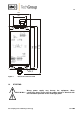
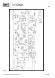
Figure 4 Assembly plan of the FA-1.4
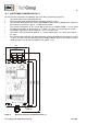
13.3 PRE-AMPLIFIER K-FA
For the electrical connection, the following steps have to be carried out (see also figure 4):
Loosen the 4 lid screws and remove the lid.
Lead the connection cable through the respective clamping screws.
The electrical connection of the sensors FA-1/2/3bi is to be made on the terminals 5 = yellow,
6 = green, 7 = white and 8 = brown, clamping block X2.
The electronic controller FA-1.. is to be mounted on clamping block X1, terminals 5 = yellow,
7 = white and 8 = brown.
The function mono-stable or bi-stable is determined via the 3 jumpers S1, S2 and S4.