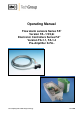
Operating Manual Flow alarm sensors Series FA® Version FA -1/2/3,bi Electronic Controllers Series FA® Version FA-1.1, FA-1.4 Pre-Amplifier K-FA.. Gas sampling and conditioning technology 5-6.
Dear customer, we have made up this operating manual in such a way that all necessary information about the product can be found and understood quickly and easily. Should you still have any question, please do not hesitate to contact M&C directly or go through your appointed dealer. Respective contact addresses are to be found in the annexe to this operating manual. Please also contact our homepage www.mc-techgroup.com for further information about our products.
Contents 1 2 3 4 5 6 General information ................................................................................................................... 4 Declaration of conformity ......................................................................................................... 4 Safety instructions ..................................................................................................................... 5 Warranty ..................................................................
Head Office M&C TechGroup Germany GmbH Rehhecke 79 40885 Ratingen Germany Telefone: 02102 / 935 - 0 Fax: 02102 / 935 - 111 E - mail: info@mc-techgroup.com www.mc-techgroup.com 1 GENERAL INFORMATION The product described in this operating manual has been examined before delivery and left our works in perfect condition related to safety regulations. In order to keep this condition and to guarantee a safe operation, it is important to heed the notes and prescriptions made in this operating manual.
3 SAFETY INSTRUCTIONS Please take care of the following basic safety procedures when mounting, starting up or operating this equipment: Read this operating manual before starting up and use of the equipment. The information and warnings given in this operating manual must be heeded. Any work on electrical equipment is only to be carried out by trained specialists as per the regulations currently in force.
5 USED TERMS AND SIGNAL INDICATIONS DANGER! This means that death, severe physical injuries and/or important material damages will occur in case the respective safety measures are not fulfilled. WARNING! This means that death, severe physical injuries and/or important material damages may occur in case the respective safety measures are not fulfilled. This means that minor physical injuries may occur in case the respective safety measures are not fulfilled.
6 INTRODUCTION The flow alarm units FA... are used for monitoring failures of sample gas or test gas in analysing equipment or analyse systems. The patented M&C flow alarm sensor FA-1/2/3bi can only be used on flow meters with meter tubes out of transparent material. By means of the optical scanning, it is possible to register also very small flow quantities for example in case of non-metallic or small particles. We can also supply a high temperature version for temperatures of up to 180°C.
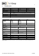
8 TECHNICAL DATA Flow alarm sensor Type Part-No. Meter tube Dimensions B x T x H in mm Weight Operating temperature Storage temperature Electrical connection Mounting Function Power supply voltage Protection type Material FA-1, bi FA-2, bi FA-3, bi 02E1000 02E2000 02E3000 5-14 mm 13-27 mm 26-55 mm 35 x 23 x 15 63 x 40 x 22 103 x 75 x 25 50 g 100 g 200 g -25°C to +70°C -25°C to +70°C 3 m connection cable standard; ø 4,5 mm, 4 cores (for each additional meter of sensor connection cable = Part-No.
9 DESCRIPTION The M&C flow alarm sensor FA-1/2/3bi consists of a compact aluminium body with a fixed, open prism and a pressure screw. This makes the positioning of the flow alarm sensors FA-1/2/3bi onto the measuring glass of the flow meter very easy; it is not necessary to disassemble the measuring glass. Three basic versions FA-1bi, FA-2bi and FA-3bi cover a measuring glass diameter range of 5-55 mm.
10 RECEIPT OF GOODS AND STORAGE Please take the flow alarm units FA... and eventual special accessories carefully out of the packaging material immediately after arrival, and compare the goods with the items listed on the packing list. Check the goods for any damage caused during delivery and, if necessary, notify your transport insurance company without delay of any damage discovered. The flow alarm units FA... are containing 1 to 4 parts depending on the desired range of delivery: 1.
12 MOUNTING Fix the flow alarm sensor , while the connection cable points to the left side (M&C-imprinting is readable) and using the locking screw onto the flow meter’s measuring tube on the desired control point for a min.-alarm (floating particle is situated in normal operation above the flow alarm sensor) in such a way that the light beam of the flow alarm sensor will not be deflected by eventual inscriptions or coloured background of the measuring tube.
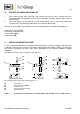
13.1 ELECTRONIC CONTROLLER FA-1.1 For the electrical connection, the following steps have to be executed (see figure 2): Loosen the 4 lid screws and remove the lid. Direct the connection cable through the respective clamping screws. The electrical connection of the sensors FA-1/2/3bi is to be made according to the colours of the terminals 5 = yellow, 6 = green, 7 = white and 8 = brown. The electrical connection of the sensor KS 2 and the pre-amplifier K-FA..
13.2 ELECTRONIC CONTROLLER FA-1.4 For the electrical connection, the following steps have to be carried out (see also figure 3): The electrical connection of the sensors FA-1/2/3bi is to be made on the terminals 5 = yellow, 6 = green, 7m = white and 8 = brown. The electrical connection of sensor KS 2 and the pre-amplifier K-FA.. is to be made on the terminals 15 = yellow, 16 = green, 17 = white and 18 = brown. The voltage supply happens on the terminals 1 = L, 2 = N and 4 = PE.
Figure 4 13.3 Assembly plan of the FA-1.4 PRE-AMPLIFIER K-FA For the electrical connection, the following steps have to be carried out (see also figure 4): Loosen the 4 lid screws and remove the lid. Lead the connection cable through the respective clamping screws. The electrical connection of the sensors FA-1/2/3bi is to be made on the terminals 5 = yellow, 6 = green, 7 = white and 8 = brown, clamping block X2. The electronic controller FA-1..
210 160 148 80 50 Ø4,3 Figure 5 14 Electrical connection K-FA STARTING WARNING! Wrong power supply may destroy the equipment. When connecting, please ensure that the supply voltage is identical with the information provided on the model type plate! Gas sampling and conditioning technology 5-6.
Without feeding of gas, the floating particle is placed on the float stopper on the bottom of the flow meter measuring glass. In case of mono-stable function, the sensor is fixed to the meter tube in such a way that the floating particle is placed on the lowest position (alarm point) and the light beam of the sensor is blacked out. For adjusting the alarm level, the float stopper must be regulated.
Adjust the voltage signal on the electronic board of the pre-amplifier K-FA.. for both photo transistors to a value between +0,08 (lowest sensitivity) to + 0,18 VDC (highest sensitivity). The tension is to be measured on the connection points of the sensor’s connection cables or the soldering points M1 – M3. The adjustment is to be made on the potentiometers P1 and P2.
15 CLOSING DOWN For closing down the equipment, no special measures are to be taken. 16 MAINTENANCE AND REPAIR NOTE! Before carrying out any maintenance or repair work, the specific safety procedures pertaining to the system and the operational process have to be observed! The flow control units series FA® are functioning without necessity of maintenance over a long time. It may be that the LED and the phototransistors of the flow alarm sensor FA-1/2/3bi must be cleaned due to dust deposits.
18 ANNEXE Circuit diagram FA1.1, 115/230V Circuit diagram FA1.1, 24VAC Circuit diagram FA1.4, 115/230V Circuit diagram FA1.4, 24V AC/DC Circuit diagram K-FA (-H) For further product documentation, please see our internet catalogue: www.mc-techgroup.com Gas sampling and conditioning technology 5-6.
Figure 6 Circuit diagram of the electronic controller FA1.1, 115/230V Gas sampling and conditioning technology 5-6.
Figure 7 Circuit diagram of the electronic controller FA1.1, 24VAC Gas sampling and conditioning technology 5-6.
Figure 8 Circuit diagram of the electronic controller FA1.4, 115/230V Gas sampling and conditioning technology 5-6.
Figure 9 Circuit diagram of the electronic controller FA1.4, 24V AC/DC Gas sampling and conditioning technology 5-6.
Figure 10 Circuit diagram of the electronic controller K-FA (-H), 115/230V Gas sampling and conditioning technology 5-6.