Operating Manual Electric gas cooler series EC® Version EC/ECS (from model nos.: 95...) Gas sampling and gas conditioning technology 3-4.
List of Contents 1 General information ...................................................................................................................5 2 Declaration of conformity ..........................................................................................................5 3 Safety instructions .....................................................................................................................6 4 Warranty .................................................................
List of Illustrations Figure 1 Figure 2 Figure 3 Figure 4 Figure 5 Figure 6 Figure 7 Figure 8 Figure 9 Figure 10 Figure 11 Figure 12 Figure 13 Figure 14 Figure 15 Figure 16 Figure 17 Example of application of EC/ECS .................................................................................... 8 EC/ECS with options EC-F and EC-FD ........................................................................... 10 Peristaltic pump SR25.2 mounted into the front panel ......................................
Dear customer, we have made up this operating manual in such a way that all necessary information about the product can be found and understood quickly and easily. Should you still have any question, please do not hesitate to contact M&C directly or go through your appointed dealer. Respective contact addresses are to be found in the annexe to this operating manual. Please also contact our homepage www.mc-techgroup.com for further information about our products.
Head Office M&C TechGroup Germany GmbH Rehhecke 79 40885 Ratingen Germany Telephone: 02102 / 935 - 0 Fax: 02102 / 935 - 111 E - mail: info@mc-techgroup.com www.mc-techgroup.com 1 GENERAL INFORMATION The product described in this operating manual has been examined before delivery and left our works in perfect condition related to safety regulations. In order to keep this condition and to guarantee a safe operation, it is important to heed the notes and prescriptions made in this operating manual.
3 SAFETY INSTRUCTIONS Please take care of the following basic safety procedures when mounting, starting up or operating this equipment: Read this operating manual before starting up and use of the equipment. The information and warnings given in this operating manual must be heeded. Any work on electrical equipment is only to be carried out by trained specialists as per the regulations currently in force.
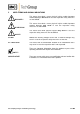
5 USED TERMS AND SIGNAL INDICATIONS DANGER! This means that death, severe physical injuries and/or important material damages will occur in case the respective safety measures are not fulfilled. WARNING! This means that death, severe physical injuries and/or important material damages may occur in case the respective safety measures are not fulfilled. This means that minor physical injuries may occur in case the respective safety measures are not fulfilled.
6 INTRODUCTION The patented M&C EC/ECS gas cooler unit is always to be installed in situations where there is interference from moisture in the gas to be measured. Reduction of the gas temperature inside the cooler to a stable and very low dew point effects a condensing-out of the sample gas. 7 APPLICATION Figure 1 shows a typical example of an application for installation of an EC/ECS gas cooler unit.
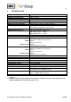
8 TECHNICAL DATA Sample outlet dew point Dew point stability Sample inlet temperature Sample inlet dew point Gas flow rate per heat exchanger Number of heat exchangers Material of heat exchangers Ambient temperature range of adjustment: +2 °C ..... +7 °C, factory setting: +5 °C at constant conditions 0,25 °C **Max. + 180°C **Max. +80°C **Max. 250l/h 1*, installation of max.
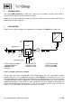
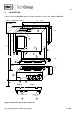
9 DESCRIPTION Figure 2 shows the EC/ECS cooler unit with the optional universal units EC-F and EC-FD. * necessary locating distance 465 84 TE 435 88 * 2HE 37,5 EC 450 ECS 360 70 240 7 HE 4 85 235 5 6,2 310 355 443 °C> ON °C< 1 A 3 2 9 45 8 1 HE Option: EC-F 100 * 3 HE 57 133 Option: EC-FD 10 SR 25 Universal unit SR 25 SR 25 SR 25 EC-FD Kondensat Aus Condensate out 100 * 12 13 View A EC/ECS max.
The EC/ECS is equally suitable for wall installation or mounting in a 19“-rack. The versions differ in the positioning of the LED function display . While for wall installation the LED function display can be fitted into the corresponding cut-outs in the EC/ECS front panel, for 19” rack mounting this is done using the cut-outs in the back panel of the casing. This positioning can be done at the factory when stating the type of installation of the EC/ECS gas cooler.
10 FUNCTION The M&C EC/ECS gas cooler is a compressor cooler with status alarm capability. This ensures 100% availability of the cooler. Up to 4 Jet-stream heat exchangers made of Duran glass, PVDF or stainless steel are located in a heat-insulated cooling block. All the heat exchangers are easily accessible and are arranged in such a way that they can be removed very simply. Figure 3 shows a schematic diagram of the functioning of the heat exchanger..
11 RECEPTION AND STORAGE The EC/ECS gas cooler is a complete pre-installed unit.
13 SUPPLY CONNECTIONS 13.1 HOSE CONNECTIONS The hoses for the heat exchangers are laid out as per Figure 3.
Condensate removal is done by customer according to the type of operation with: - Automatic float-type condensate traps AD-... only for over-pressure operation; Stainless steel heat exchangers with G 3/8“ thread joint can be directly fitted up with the float-type condensate trap AD-SS by means of a thread adapter part number FF 11000 (1/2“ NPT to G 3/8“i). By this wall mounting of the ADN O T E ! SS unit isn’t necessary! - Condensate collector container that is emptied manually; - peristaltic pump.
Figure 4 shows the electrical connections at the plastic housing behind the front panel of the EC/ECS casing (Fig. 2). EC automatic control electronics Supply main 18 19 20 Status alarm L N PE NC MC NO NC MC NO Clamp connection X0 (from model nos. 96...
Before model nos. 96... the pin configuration for power and alarm connection was as follows: The power connector is on the front panel of the EC automatic control board. This is within the plastic housing, behind the removable front panel of the cooler unit. The pin arrangement of the power connector is as shown below (Fig.
The following steps should be carried out before initial start-up: Connect the cooler unit to the mains power supply; Check that the equipment is connected to the correct mains voltage, 115V or 230V, as shown on the type plate! Lead the status contacts for reporting of under- and over-temperature to the measuring station; NOTE! 14.
15 CLOSING DOWN NOTE! The location for the cooler must remain frost-free, even when the unit has been switched off! If the cooler unit is putting out of action for a short time no particular measures need to be taken. We recommended sweeping the cooler with inert gas or ambient air while the unit is putting out of action for a longer time. WARNING! 16 Aggressive condensate is possible.
When using automatic condensate removal by means of peristaltic pumps, the hoses of the peristaltic pumps must be checked every three or six months, depending on the operating conditions, and replaced if necessary. The procedure for changing the hoses is given in the corresponding operating instruction SR25. 16.2 ADDING AND REPLACING THE HEAT EXCHANGERS Removal of the heat exchangers may be necessary to carry out maintenance or repair work.
DANGER Dangerous voltage! It is necessary to take the pump off the mains before any assembly, maintenance and repair work is carried out! Flexible tube, conveying belt, contact pulleys and contact springs are the only parts of the pump subject to wear. They are simple to change. 16.3.
NOTE! Only the usage of the original hose set guarantees a perfect function. Never lubricate the hose. Before mounting the pump check all parts for impurity and clean if necessary. Put the conveying belt with the new hose into the dovetail guide of the pump body; Press conveying belt at the recessed grips and simultaneously turn the S-bolt anticlockwise until it snaps; Switch on pump. 16.3.
17 TROUBLE SHOOTING Troubleshooting is made much easier by the LED function display. The following table shows possible reasons for error and how to correct them (not applicable for the running-up phase of the cooler).
LED display Function error and status alarm Equipment does not cool; Probable cause Checking / Correction Ambient Ambient temperature must be ≥ 8°C! temperature < 2°C °C > ON green °C < red Cooler has been Cooling over-cooled (temp. compressor < 2°C); stopped; Check temperature at EC automatic control board (18.2); If temperature < 2°C (< 0,2V): Check PT100 temperature sensor (19); If not OK: Replace sensor.
18 EC AUTOMATIC CONTROL BOARD Figure 8 shows the arrangement of the EC automatic control board (wiring scheme in Appendix). Figure 9 EC automatic control board Gas sampling and gas conditioning technology 3-4.
18.1 CONNECTING THE COOLING COMPRESSOR The cooling compressor is connected to the EC automatic control board (Fig. 8). Figure 9 shows the connection diagram for the compressor. cable Nr.1 from EC automatic control board pin 21 cable Nr.2 from EC automatic control board pin 24 cable Nr.3 from EC automatic control board pin 22 PE green/yellow from EC automatic control board pin 23 Condenser Connection cable Art.Nr.: KL0001 cable Nr.1 230V 80uF Art.Nr.:90K1055 PE green/ yellow 115V 160uF Art.Nr.
18.2 TEMPERATURE SETTING FOR THE EC/ECS COOLER The EC/ECS gas cooler is set at the factory to a regulated temperature of +5°C. Setting of the regulated temperature is done by trimming potentiometer P3, on the EC automatic control board of the cooler. The setting range covers from 0°C to 20°C. Turning it to the right sets a lower temperature, and turning it to the left sets a higher temperature.
19 CHECKING THE TEMPERATURE SENSOR The EC/ECS cooler temperature sensor is a PT100 element as from serial numbers 95... . There are two methods for checking the PT100 element, as follows: 1. Voltage method In order to check the sensor for the cooler currently in operation, the actual voltage at the measuring sockets 1 and 2 of the EC automatic control board must be measured as per section 18.2 above. Figure 10 shows the voltage characteristics in relation to temperature.
20 CHANGING THE COOLER AGGREGATE NOTE! Before removing the cooler aggregate disconnect the cooler from all power supplies; Before mounting the new aggregate check, if voltage corresponds with the specification on the type plate; changing the cooler aggregate may only be carried out by qualified personnel! According to the cooler version, forced ventilated or not, cooler aggregates with differing quantity of refrigerant are available (spare parts list).
For changing the cooler aggregate please carry out the following steps: Remove the heat exchangers (16.2); Loosen the fastening screws from the front panel of the cooler casing (Fig.
21 RETROFITTING A DIGITAL TEMPERATURE INDICATION 21.1 DATA FOR MOUNTING Display LCD 10mm, unit °C Display range -30°C to +30°C Measuring period 2,5 per second Ambient temperature range 0°C to +50°C Main supply 4,5V to 15V, 2mA Housing ABS plastics black Protection IP50 for the front IP00 for the back (DIN 40050) Locating distance 30,5mm x 57mm (H x W) Fitting length 73mm Data according to the technical description DPM 528, Schwille Elektronik. 21.
For mounting the display and the temperature sensor please notice the following: Loosen up the fixing screws of the front panel and remove it (see operating manual EC/ECS); Remove the cooler cover (see operating manual EC/ECS); Make the cut-out for the temperature display into the front panel according to the locating distance shown in figure 13; For cable bushings through the plastic housing of the EC/ECS control board please use the available PG9 cable glands. 21.
22 SPARE PARTS LIST Wear, tear and replacement part requirements depend on specific operating conditions. The recommended quantities are based on experience and are not binding.
23 APPENDIX Sample output dew point (ambient temperature 20°C) depending on gas flow rate Circuit diagram EC automatic control board, drawing number : 2300 - 5.04.2 Wiring plan automatic condensate removal unit EC-FD, drawing number : 2300-5.05.0 More product documentation is available on our Internet catalogue: www.mc-techgroup.com Instruction manual peristaltic pump SR 25.1, Document : 3-7.1-MD; Condensate vessel TG, TK Document : 3-6.3.1 GL-connectors Document : 3-5.1.
Sample output dew point (ambient temperature 20°C) depending on gas flow rate sample inlet dew point Gasausgangs-Taupunkt Sample outlet dewpoint 60°C 40°C °C 10 EC-G 5 N l/h 62,5 MessgasDurchfluss 125 187,5 Gas flow rate 250 Gasausgangs-Taupunkt Sample outlet dewpoint °C 10 EC-SS 5 N l/h 62,5 MessgasDurchfluss 125 187,5 250 Gas flow rate Gasausgangs-Taupunkt Sample outlet dewpoint °C 10 EC-PV 5 N l/h 62,5 MessgasDurchfluss 125 187,5 250 Gas flow rate Figure 15 Sample outlet dew
Figure 16 Circuit diagram EC automatic control board Gas sampling and gas conditioning technology 3-4.
Universaleinheit EC-FD 2300-5.05.0 37 Figure 17 Wiring plan automatic condensate removal unit EC-FD Gas sampling and gas conditioning technology 3-4.