
Operator's manual Manual

3
Gas sampling and gas conditioning technology 3-1.1-ME
List of Contents
1 General information ..................................................................................................................... 4
2 Declaration of conformity ........................................................................................................... 4
3 Safety instructions ....................................................................................................................... 5
4 Warranty ....................................................................................................................................... 5
5 Used terms and signal indications ............................................................................................. 6
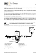
6 Application ................................................................................................................................... 7
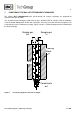
7 Function of the M&C Jet-stream heat exchanger ..................................................................... 8
8 Technical data .............................................................................................................................. 9
9 Description ................................................................................................................................. 10
10 Receipt of goods and storage .................................................................................................. 11
11 Installation instructions ............................................................................................................ 12
12 Supply connections ................................................................................................................... 12
12.1 Hose connections ................................................................................................................ 12
12.2 Electrical connections ......................................................................................................... 13
13 Starting ....................................................................................................................................... 14
13.1 Function sequence and LED function display ..................................................................... 15
14 Closing down ............................................................................................................................. 15
15 Maintanance ............................................................................................................................... 16
15.1 Adding and replacing the heat exchangers ......................................................................... 16
16 Trouble shooting........................................................................................................................ 18
17 Temperature setting and control the ECP cooler ................................................................... 19
18 Checking the temperature sensor ............................................................................................ 20
19 Spare parts list ........................................................................................................................... 21
20 Appendix .................................................................................................................................... 23
List of Figures
Figure 1 Application example ECP .000 ............................................................................................. 7
Figure 2 Functioning diagram of the heat exchanger ......................................................................... 8
Figure 3 Electric gas cooler ECP .000 .............................................................................................. 10
Figure 4 Terminals for mains supply and temperature alarm ........................................................... 14
Figure 5 Temperature adjustment .................................................................................................... 19
Figure 6 Voltage in relation to the temperature of the cooler ............................................................ 20
Figure 7 Resistance temperature characteristics of the PT100 temperature sensor ........................ 20
Figure 8 Sample output dew point (ambient temperature 20°C) depending on gas flow rate .......... 24
Figure 9 Dimensions of the cooler Type ECP 1000/2000/3000 ........................................................ 25
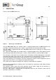
Figure 10 Set-up diagram ................................................................................................................... 26
Figure 11 Electronic board and main board up to 2006 ...................................................................... 27
Figure 12 Electronic board and main board from 2007 on ................................................................. 28
Figure 13 Circuit diagram up to 2006 ................................................................................................. 29
Figure 14 Circuit diagram from 2007 on ............................................................................................. 30