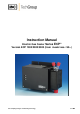
Instruction Manual Electric Gas Cooler Series ECP ® Version ECP 1000/2000/3000 (from model nos.: 95...) Gas sampling and gas conditioning technology 3-1.
Dear customer, we have made up this operating manual in such a way that all necessary information about the product can be found and understood quickly and easily. Should you still have any question, please do not hesitate to contact M&C directly or go through your appointed dealer. Respective contact addresses are to be found in the annexe to this operating manual. Please also contact our homepage www.mc-techgroup.com for further information about our products.
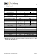
List of Contents 1 General information ..................................................................................................................... 4 2 Declaration of conformity ........................................................................................................... 4 3 Safety instructions....................................................................................................................... 5 4 Warranty ..........................................................
Head Office M&C TechGroup Germany GmbH Rehhecke 79 40885 Ratingen Germany Telephone: 02102 / 935 - 0 Fax: 02102 / 935 - 111 E - mail: info@mc-techgroup.com www.mc-techgroup.com 1 GENERAL INFORMATION The product described in this operating manual has been examined before delivery and left our works in perfect condition related to safety regulations. In order to keep this condition and to guarantee a safe operation, it is important to heed the notes and prescriptions made in this operating manual.
3 SAFETY INSTRUCTIONS Please take care of the following basic safety procedures when mounting, starting up or operating this equipment: Read this operating manual before starting up and use of the equipment. The information and warnings given in this operating manual must be heeded. Any work on electrical equipment is only to be carried out by trained specialists as per the regulations currently in force.
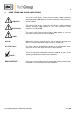
5 USED TERMS AND SIGNAL INDICATIONS DANGER! This means that death, severe physical injuries and/or important material damages will occur in case the respective safety measures are not fulfilled. WARNING! This means that death, severe physical injuries and/or important material damages may occur in case the respective safety measures are not fulfilled. This means that minor physical injuries may occur in case the respective safety measures are not fulfilled.
6 APPLICATION The Peltier Gas Sample Cooler Type ECP .000 is used in analyser sample system design to reduce the dew point of wet gases to a level that is stable and low. Sample gas cooling prevents subsequent condensation in the analyser. The stability of the dew point is also extremely important at it helps to prevent water vapour cross sensitivity and volumetric error, especially in infrared analysers. The sample gas passes through a sampling probe to the Type ECP .
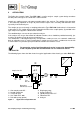
7 FUNCTION OF THE M&C JET-STREAM HEAT EXCHANGER The coolers ECP 1000/2000/3000 with special design for analysis technique are prepared for maximum flow rates of 350l/h. The Jet-Stream heat exchangers made of Duran glass, optional PVDF or stainless steel are located in a heat insulated cooling block. All the heat exchangers are easily accessible and are arranged in such a way that they can be removed very simply. Figure 2 shows a schematic diagram of the functioning of the heat exchanger.
8 TECHNICAL DATA Electro Gas Cooler Version Sample outlet dew point Dew point stability Sample inlet temperature*** Sample inlet dew point*** Gas flow rate/heat exchanger*** Number of heat exchangers Material of heat exchangers Ambient temperature*** Storage temperature Pressure Total cooling power at +25°C ambient Dead volume/heat exchanger P/heat exchanger Sample gas connection Condensate connection Ready for operation Power consumption Mains power supply Electrical connections Alarm contact Contact
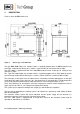
9 DESCRIPTION Figure 3 shows the ECP cooler unit. (305) Figure 3 Electric gas cooler ECP .000 The type ECP 1000 Peltier Gas Sample Cooler is supplied complete with an ECPJet-Stream heat exchanger made either of Duran glass, stainless steel or PVDF for a maximum flow of 150l/h. The ECP 2000 is supplied with two ECP 1000 ECPJet-Stream heat exchanger for cooling of two channels a’ 150l/h.
There are three LED status indicators: Upper red LED " > °C " Central green LED "On", lights or pulsates Lower red LED " < °C " = Temperature alarm (T> +8°C) = Cooler on = Temperature alarm (T< +2°C) The green LED alone indicates that the specifications with regard to dew point temperature and dew point stability are achieved. The red LED lights to indicates that the control system has deviated from the setpoint by more than 3°C. The upper red LED " > °C " lights up to indicate an overload, i.e.
11 INSTALLATION INSTRUCTIONS The ECP .000 Peltier Gas Cooler is designed for wall or panel mounting.
NOTE! When fixing the connectors in the PVDF heat exchanger hold up with a wrench at the pane of the bolt head! Option: stainless steel heat exchanger with NPT The heat exchangers with NPT threaded connectors are marked with circulated notches. The NPT thread must be screwed in with sealant or fixed with adhesive.
Coolers from serial nos.: 95.. also have a mains selector (S1) on the basic board for either 230V 50Hz or 115V 60Hz operation on the basic circuit board (see circuit diagram in appendix). Before commissioning, use a screwdriver to turn the selector to the correct position 230/115 depending on your main power input supply. The status alarm contact for indicating and isolating the gas supply must be incorporated into the equipment control system.
13.1 FUNCTION SEQUENCE AND LED FUNCTION DISPLAY Three function display LED’s are provided to give a visualisation of the function sequence during startup of the cooler. The top LED (red) indicates that the temperature set by the ECP automatic control electronics has been exceeded or has not been reached. The central green LED shows that the cooler is operating. The bottom red function display LED gives an alarm if the temperature falls too low.
15 MAINTANANCE Before the maintenance work is carried out, it is necessary that the specific safety procedures pertaining to the system and operational process be observed! WARNING! It is necessary to take the ECP electric gas cooler off the mains before any assembly, maintenance or repair work is carried out! The ECP ..000 Gas Cooler requires no particular routine maintenance.
Mounting the Duran glass heat exchangers please notice: Check the PTFE/Silicon locking Rings for damage. In assembly, the locking rings must have the PTFE side facing the medium, Otherwise the required degree of sealing cannot be guaranteed; Do up the red GL coupling rings hand-tight by turning them to the right; Gas sampling and gas conditioning technology 3-1.
16 TROUBLE SHOOTING The following table aims to point out possible operational problems and offer solutions to such problems (not applicable during the starting procedure). Problem/Indication ECP .000 is not cooling °C > Possible cause Action/Check No mains supply Check for mains supply voltage at terminals L&N, X1/1+2 against nameplate. If OK, check fuses F1, F2. Ambient temperature +2°C T +5°C Check ambient temperature. ON °C < °C > red ON °C < ECP .
17 TEMPERATURE SETTING AND CONTROL THE ECP COOLER The gas cooler is set by manufacturer to a control temperature of +5°C. This temperature can be adjusted with a trimmer Potentiometer P3 within a range of 0°C to +20°C. This Potentiometer is located in the ECP ..000 case behind the front sheet metal. Turning clockwise will increase the temperature and turning counter clock will decrease the temperature respectively.
18 CHECKING THE TEMPERATURE SENSOR The ECP .000 cooler temperature sensor is a PT100 element as from serial numbers 95... . There are two methods for checking the PT100 element, as follows: 1. Voltage method In order to check the sensor for the cooler currently in operation, the actual voltage at the corresponding measuring sockets must be measured (see ‘Temperature Setting and Control’). The following figure shows the voltage characteristics in relation to temperature.
19 SPARE PARTS LIST Wear, tear and replacement part requirements depend on specific operating conditions. The recommended quantities are based on experience and are not binding. Electric Gas Cooler ECP1000/2000/3000 (C) consumable parts, (R) recommended spare parts, (S) spare parts recommended quantity ECP...
Electric Gas Cooler ECP1000/2000/3000 (C) consumable parts, (R) recommended spare parts, (S) spare parts recommended quantity ECP... being in operation [years] C/R/S 1 2 3 93 K 0020 ECP Electronic Board complete from serial nos.: 95... R - - 1 93 K 0530 ECP Mains Board complete from serial nos.: 95... R - - 1 90 K 2010 Rectifier for ECP2000/3000 and ECP1000 as from s.no.:95xx R - 1 1 93 K 0040 PT100 sensor incl.
20 APPENDIX Sample output dew point (ambient temperature 20°C) depending on gas flow rate Dimensions of the Cooler Type 1000/2000/3000 Set-up diagram Components of main -and electronic board up to 2006 and from 2007 on Circuit diagram ECP .000, up to 2006 and from 2007 on Drawing number : 2413-5.01.1 and 2413-5.03.0 For additional manuals and data sheets please look on our home page www.mc-techgroup.com Instruction manual peristaltic pump SR 25.1, Document : 3-7.
Sample inlet dew point 50°C Gasausgangs-Taupunkt Sample outlet dewpoint °C 10 Glaswärmetauscher Heatexchanger out of glass PVDF Wärmetauscher Heatexchanger out of PVDF Rostf. Stahl Wärmetauscher Heatexchanger out of SS316 ECP 1000 5 N l/h 50 Messgas-Durchfluss 150 100 Gas flow rate Gasausgangs-Taupunkt Sample outlet dewpoint °C 10 Glaswärmetauscher Heatexchanger out of glass PVDF Wärmetauscher Heatexchanger out of PVDF Rostf.
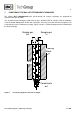
ECP 1000 ECP 2000 GL18 215 137 63 11 6 GL18 25 17 >°C 180 >°C ON 200 220 ON 220 <°C <°C ECP 2000 Cooler ECP Cooler 1000 2xPG 11 2xPG 11 GL25 275 30 305 GL25 55 25 68 26 136 ECP 3000 25 GL1 8 220 >°C O N <°C ECP Cooler 3000 2xPG 11 GL25 305 45 Figure 9 Dimensions of the cooler Type ECP 1000/2000/3000 Gas sampling and gas conditioning technology 3-1.
GL 18 Temperature sensor PT100 **install the sensor with thermal conductivity paste Control electronic board X5 Pelt.Pelt.+ PT100 PT100 Fan Fan + 1 2 3 4 5 6 Electronic housing Fan Mains electronic board Figure 10 Cooling block GL 25 Peltier element **install with thermal conductivity paste Set-up diagram Gas sampling and gas conditioning technology 3-1.
Electronic board up to 2006 Main board up to 2006 Figure 11 Electronic board and main board up to 2006 Gas sampling and gas conditioning technology 3-1.
Electronic board from 2007 on Main board from 2007 on X5 Figure 12 Electronic board and main board from 2007 on Gas sampling and gas conditioning technology 3-1.
Figure 13 Circuit diagram up to 2006 Gas sampling and gas conditioning technology 3-1.
Figure 14 Circuit diagram from 2007 on Gas sampling and gas conditioning technology 3-1.