Instruction Manual Electric Gas Cooler Series ECP ® Versions ECP20-1 and ECP20-2 (from model nos.: 95...) Gas sampling and gas conditioning technology 3-1.
Dear customer, we have made up this operating manual in such a way that all necessary information about the product can be found and understood quickly and easily. Should you still have any question, please do not hesitate to contact M&C directly or go through your appointed dealer. Respective contact addresses are to be found in the annexe to this operating manual. Please also contact our homepage www.mc-techgroup.com for further information about our products.
List of Contents 1 General information ................................................................................................................ 4 2 Declaration of conformity....................................................................................................... 4 3 Safety instructions .................................................................................................................. 5 4 Warranty ........................................................................
Head Office M&C TechGroup Germany GmbH Rehhecke 79 40885 Ratingen Germany Telephone: 02102 / 935 - 0 Fax: 02102 / 935 - 111 E - mail: info@mc-techgroup.com www.mc-techgroup.com 1 GENERAL INFORMATION The product described in this operating manual has been examined before delivery and left our works in perfect condition related to safety regulations. In order to keep this condition and to guarantee a safe operation, it is important to heed the notes and prescriptions made in this operating manual.
3 SAFETY INSTRUCTIONS Please take care of the following basic safety procedures when mounting, starting up or operating this equipment: Read this operating manual before starting up and use of the equipment. The information and warnings given in this operating manual must be heeded. Any work on electrical equipment is only to be carried out by trained specialists as per the regulations currently in force.
5 USED TERMS AND SIGNAL INDICATIONS DANGER! This means that death, severe physical injuries and/or important material damages will occur in case the respective safety measures are not fulfilled. WARNING! This means that death, severe physical injuries and/or important material damages may occur in case the respective safety measures are not fulfilled. This means that minor physical injuries may occur in case the respective safety measures are not fulfilled.
6 APPLICATION The Peltier Gas Sample Cooler Type ECP20 is used in analyser sample system design to reduce the dew point of wet gases to a level that is stable and low. Sample gas cooling prevents subsequent condensation in the analyser. The stability of the dew point is also extremely important at it helps to prevent water vapour cross sensitivity and volumetric error, especially in infrared analysers.
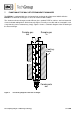
7 FUNCTION OF THE M&C JET-STREAM HEAT EXCHANGER The ECP20-1 is equipped with one Jet-Stream heat exchanger for a flow rate of 250l/h while the ECP20-2 has two heat exchangers in series for maximum flow of 500l/h. The Jet-Stream heat exchangers made of Duran glass, optional PVDF or stainless steel are located in a heat-insulated cooling block. All the heat exchangers are easily accessible and are arranged in such a way that they can be removed very simply.
8 TECHNICAL DATA Electric Gas Cooler ECP Sample outlet dew point Type ECP20-1 Type ECP20-2 range of adjustment: +2 °C ..... +15 °C, factory setting: +5 °C Dew point stability at const. conditions: < ±0,1°C Sample inlet temperature **max. 180°C Sample inlet dew point **max. 80°C Gas flow rate Number of heat exchangers Material of heat exchangers **max.250l/h **max.
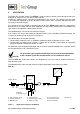
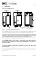
9 DESCRIPTION Figure 3 shows the ECP cooler unit. ECP20-2G ECP20-1G Figure 3 Netz/Power supply PG11 Alarmkontakt PG11 Alarm Contact PG11 Electric gas cooler ECP20-1 and ECP20-2 The type ECP20-1 Peltier Gas Sample Cooler is supplied completely with an EC Jet-Stream heat exchanger made either of Duran glass, stainless steel or PVDF for a maximum flow of 250l/h.
The electronic control system with status indication and the power supply unit are housed in a protective aluminium enclosure on the front panel of the cooler. There are three LED status indicators : Upper red LED "°C >" = Temperature alarm > +8°C Central green LED "On", lights or pulsates = Cooler on Lower red LED "°C <" = Temperature alarm < +2°C The green LED alone indicates that the specifications with regard to dew point temperature and dew point stability are achieved.
10 RECEIPT OF GOODS AND STORAGE The ECP gas cooler is a complete pre-installed unit.
12 SUPPLY CONNECTIONS 12.1 HOSE CONNECTIONS The gas inlet and outlet is located on the top of the cooler and is indicated by arrows on the ECP JetStream heat exchangers. For possible connectors see technical data. Correspondingly tube or hose connectors are optional available by M&C.
12.2 ELECTRICAL CONNECTIONS When connecting the equipment, please ensure that the supply voltage is identical with the information provided on the model type plate.
13 STARTING Before using the equipment for the first time, check that the safety measures specific to the installation and process are complied with! The automatic control electronics of the ECP 20 permit automatic start-up of the cooler. The error diagnostics guarantee full monitoring and reporting of possible sources of error. The following description is valid for start-up of the gas cooler for an ambient temperature > 8°C.
14 CLOSING DOWN NOTE! The area in which the cooler is situated when not in use must be kept free of frost at all times! If the cooler unit is putting out of action for a short time no particular measures need to be taken. We recommended sweeping the cooler with inert gas or ambient air while the unit is putting out of action for a longer time. Condensate has to be removed completely from the cooler. WARNING! 15 Aggressive condensate possible.
15.1 ADDING AND REPLACING THE HEAT EXCHANGERS Removal of the heat exchangers may be necessary to carry out maintenance or repair work. We recommend the following procedures and in this order for replacement of the heat exchangers: Release the upper gas connections and lower condensate connections; WARNING! Aggressive condensate is possible.
16 TROUBLE SHOOTING The following table aims to point out possible operational problems and offer solutions to such problems (not applicable during the starting procedure). Problem/Indication Possible cause ECP20 is not cooling No mains supply Action/Check Check for mains supply voltage at terminals L&N, X1/1+2 against nameplate. If OK, check fuses F1, F2. °C > ON Ambient temperature +2°C T +5°C Check ambient temperature.
17 TEMPERATURE SETTING AND CONTROL THE ECP COOLER The gas cooler is set by manufacturer to a control temperature of +5°C. Temperature - + 100mV/°C This temperature can be adjusted with a trimmer Potentiometer P3 within a range of 0°C to +20°C. P3 Current temperature This Potentiometer is located on the ECP20 control board. Ri>100K Turning clockwise will increase the temperature and turning counterclock will decrease the temperature respectively.
2. Resistance method In this case the sensor must be disconnected from pins X5/5+6 at the ECP20 automatic control board and removed from the cooling block. When measuring the resistance of the PT100 element, this must be proportional to the ambient temperature. The resistance-temperature characteristics are shown in the figure below.
19 SPARE PARTS LIST Wear, tear and replacement part requirements depend on specific operating conditions. The recommended quantities are based on experience and are not binding. Electric Gas Cooler ECP20-1, ECP20-2 (C) consumable parts, (R) recommended spare parts, (S) spare parts recommended quantity ECP...
Electric Gas Cooler ECP20-1, ECP20-2 (C) consumable parts, (R) recommended spare parts, (S) spare parts recommended quantity ECP...
20 APPENDIX Sample output dew point (ambient temperature 20°C) depending on gas flow rate Circuit diagram ECP20, Drawing number : 2388-5.01.1 More product documentation is available on our Internet catalogue: www.mc-techgroup.com. Instruction manual peristaltic pump SR 25.1, Document : 3-7.1-MD; Condensate vessel TG, TK Document : 3-6.3.1 GL-connectors Document : 3-5.1.1 Automatic liquid drain AD-SS Document : 3-6.2.3 Automatic liquid drain AD-P Document : 3-6.2.
Cooler EC-G / ECP-20 with Duran Glass Heat Exchanger Outlet dew point [°C] 10 9 8 7 6 5 4 Ambient temperature 20°C Inlet dew point: 60°C 40°C 50 100 150 200 250 Sample gas flow [Nl/h] Cooler EC-G / ECP-20 with SS 316 Heat Exchanger Outlet dew point [°C] Inlet dew point: 10 9 8 7 6 5 4 60°C 40°C 50 100 150 200 250 Sample gas flow [Nl/h] Cooler EC-PV / ECP-20 with PVDF Heat Exchanger Inlet dew point: 10 9 Outlet 8 dew point [°C] 7 6 5 4 60°C Ambient temperature 20°C 40°C 50 100
Figure 8 Circuit diagram ECP-20 from 07/97 on Gas sampling and gas conditioning technology 3-1.