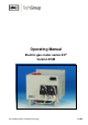
Operating Manual Electric gas cooler series EC® Version ECM Gas sampling and gas conditioning technology 3-3.
Dear customer, we have made up this operating manual in such a way that all necessary information about the product can be found and understood quickly and easily. Should you still have any question, please do not hesitate to contact M&C directly or go through your appointed dealer. Respective contact addresses are to be found in the annexe to this operating manual. Please also contact our homepage www.mc-techgroup.com for further information about our products.
Content 1 2 3 4 5 6 General information ................................................................................................................... 4 Declaration of conformity ......................................................................................................... 4 Safety instructions ..................................................................................................................... 5 Warranty ...................................................................
Head Office M&C TechGroup Germany GmbH Rehhecke 79 40885 Ratingen Germany Telephone: 02102 / 935 - 0 Fax: 02102 / 935 - 111 E - mail: info@mc-techgroup.com www.mc-techgroup.com 1 GENERAL INFORMATION The product described in this operating manual has been examined before delivery and left our works in perfect condition related to safety regulations. In order to keep this condition and to guarantee a safe operation, it is important to heed the notes and prescriptions made in this operating manual.
3 SAFETY INSTRUCTIONS Please take care of the following basic safety procedures when mounting, starting up or operating this equipment: Read this operating manual before starting up and use of the equipment. The information and warnings given in this operating manual must be heeded. Any work on electrical equipment is only to be carried out by trained specialists as per the regulations currently in force.
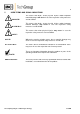
5 USED TERMS AND SIGNAL INDICATIONS DANGER! This means that death, severe physical injuries and/or important material damages will occur in case the respective safety measures are not fulfilled. WARNING! This means that death, severe physical injuries and/or important material damages may occur in case the respective safety measures are not fulfilled. This means that minor physical injuries may occur in case the respective safety measures are not fulfilled.
6 INTRODUCTION The patented M&C ECM gas cooler unit is always to be installed in situations where there is interference from moisture in the gas to be measured. Reduction of the gas temperature inside the cooler to a stable and very low dew point effects a condensing-out of the sample gas. 6.1 SERIAL NUMBER The type plate with the serial number is located at the side panel of the cooler housing (wall mounting version).
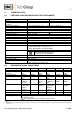
8 TECHNICAL DATA 8.1 FOR BASIC COOLER ECM WITHOUT HEAT EXCHANGER Gas cooler series EC Part No.
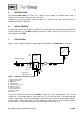
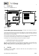
9 DESCRIPTION Figure 2 shows the ECM-2G cooler unit. Min. side distance 100 100 270 208 270 6 46 204 11 220 ventilation opening 240 Cooler EC M Compressor ventilation outlet 30 50 84 Dimensions in mm Figure 2 ECM-2G The cooler ECM is equally suitable for wall installation. The depth of the housing of the cooler is 270mm (316mm with optional mounted peristaltic pumps ). On the upper side of the cooler casing you will see the cutouts for 1 or 2 heat exchangers.
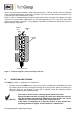
Up to 2 Jet-stream heat exchangers made of Borosilicate glass, PVDF or stainless steel are located in a heat-insulated cooling block. All the heat exchangers are easily accessible and are arranged in such a way that they can be removed very simply. Figure 3 shows a schematic diagram of the functioning of the heat exchanger: The compressor cooler system has a heat-insulated cooling block at a constant temperature of +5°C.
12 INSTALLATION INSTRUCTIONS The ECM cooler is suitable for wall mounting. NOTE! The operating position for this cooler is exclusively vertical. This is the only way to ensure proper separation and removal of condensate in the heat exchangers. During transport and installation, the cooler must always be stood up with the transport feet positioned underneath so that the oil in the closed compressor circuit cannot run out of the compressor case.
NOTE! Do not mix up the hose connections; the inlet and outlet connections of the heat exchangers are marked with arrows; Ensure that the connections are sealed adequately; To ensure free removal of the condensate, ensure that the listed diameters for the condensate removal lines are not reduced! Ensure that the connections are sealed adequately by noting the following: Borosilicate glass heat exchangers with connections GL18-6 respectively GL25-12 (standard) Before assembly, check the GL coupling
13.2 ELECTRICAL CONNECTIONS CARE! NOTE! WARNING! When connecting the equipment, please ensure that the supply voltage is identical with the information provided on the model type plate! Attention must be paid to the requirements of IEC 364 (DIN VDE 0100) when setting high-power electrical units with nominal voltages of up to 1000V, together with the associated standards and stipulations. An external main switch must be provided.
14 START-UP The thermo-hydraulic controlled cooling system of the ECM permit automatic start-up of the cooler. The following description is valid for start-up of the gas cooler for an ambient temperature > 8°C. Before starting up the gas cooler, it must be placed in its operating position for at least two hours. The liquid inside the system may have been redistributed, and this could cause problems in operating.
16 MAINTENANCE The safety instructions specific to the plant and process are to be consulted prior to any maintenance work! Dangerous voltage! It is necessary to take the gas cooler off the mains before any DANGER! assembly, maintenance and repair work is carried out! The ECM cooler does not require any special maintenance intervals. The cooler is to be cleaned with compressed air according to the contamination level of the ambient air. 16.
16.2 CLEANING THE FINS OF THE CONDENSER Dust on the fins of the condenser reduces the cooling capacity. Therefore it is necessary to clean the fins from time to time. The following steps are recommended: Shut off the gasflow; Dismantle the tubing for gas in- and outlet; Unscrew the cooler hood and remove it carefully; Clean the fins carefully with compressed air; Re-install the cooler hood; Connect the tubing for gas in- and outlet. NOTE! 16.
2 4 Figure 6 3 Change of the pump tube Take off the cooler of the mains; Open hose connectors at the pump; Press conveying belt at the recessed grips and turn Sbolt 2 clockwise up to limit stop; Take away conveying belt and remove the old hose set from the guides by the hose connectors; Press the two contact pulleys and check whether the spring pressure is still sufficient, if not, the contact springs have to be changed; Put the new hose set with the hose connectors into t
While mounting pay attention to the fit of ‘rotational axisdriver’. Use genuine spare parts only! NOTE! 16.3.3 CLEANING THE PUMP HEAD When changing flexible tube or other parts, inspect all parts for dirt before assembling the pump head and clean them if necessary. As far as possible clean the parts with a dry cloth. Solvents should not be used as they can attack the plastics and synthetic rubber parts. If a compressed air line is available, blow the parts out with it.
18 TROUBLE SHOOTING The following table should give an overview of possible errors and an instruction to check and to repair them (is not valid for the starting-up period of cooler).
19 SPARE PARTS LIST Wear, tear and replacement part requirements depend on specific operating conditions. The recommended quantities are based on experience and they are not binding. Electric gas cooler ECM (C) Consumable parts (R) Recommended spare parts (S) Spare parts Part No.
20 APPENDIX Sample output dew point depending on gas flow rate at sample inlet dew points of 60C Circuit diagram ECM Drawing No.: 2456-5.01.0 Certificate of compliance Further product documentation can be seen and downloaded from our home page: www.mc-techgroup.com Threaded couplings for ”GL” glass connections Document: 3-5.1.1 Instruction manual peristaltic pump SR25.1 Document: 3-7.1ME Automatic liquid drain AD-SS Document: 3-6.2.3 Automatic liquid drain AD-P Document: 3-6.2.
Figure 9 Circuit diagram ECM Gas sampling and gas conditioning technology 3-3.
Gas sampling and gas conditioning technology 3-3.
Gas sampling and gas conditioning technology 3-3.
Gas sampling and gas conditioning technology 3-3.