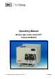
Operating Manual Electric gas cooler series EC® Version ECM-ExII Gas sampling and gas conditioning technology 3-3.
Dear customer, we have made up this operating manual in such a way that all necessary information about the product can be found and understood quickly and easily. Should you still have any question, please do not hesitate to contact M&C directly or go through your appointed dealer. Respective contact addresses are to be found in the annexe to this operating manual. Please also contact our homepage www.mc-techgroup.com for further information about our products.
Content 1 2 3 4 5 6 7 8 General information .................................................................................................................. 4 Declaration of conformity......................................................................................................... 4 Electrical standards .................................................................................................................. 5 Safety instructions ........................................................
Head Office M&C TechGroup Germany GmbH Rehhecke 79 40885 Ratingen Germany Telephone: 02102 / 935 - 0 Fax: 02102 / 935 - 111 E - mail: info@mc-techgroup.com www.mc-techgroup.com 1 GENERAL INFORMATION The product described in this operating manual has been examined before delivery and left our works in perfect condition related to safety regulations. In order to keep this condition and to guarantee a safe operation, it is important to heed the notes and prescriptions made in this operating manual.
3 ELECTRICAL STANDARDS The electrical standard of electrical equipment corresponds to the safety regulations concerning the EN61010; CAN/CSA-C22.2 No 61010.1-04 , UL Std. No 61010-1(2 Edition) EN 60079-15:2003. According to NEC 500: Class I, Div. 2, Groups A/B/C/D, T4 CAN/CSA-C22.2 No 61010.1-4 and No. 213-M87M; for 115V Approval Standard Class No. 3611.
5 INFORMATION AND SAFETY INSTRUCTIONS FOR USING THE COOLER IN HAZARDOUS AREAS The compressor cooler ECM-ExII is suitable for using in hazardous area category 3G. The explosion proof protection is: 230V / 115 : II 3 G EEx nAC [nL] IIC T4 (appr.-no.: 02 ATEX 1040X) 230V / 115V : Class I, Div. 2, Groups A/B/C/D, T4 / CAN/CSA-C22.2 No 61010.1-4; No. 213-M87 115V : Class I, Div. 2, Groups A/B/C/D, T4 FM Approval Standard Class No.
7 USED TERMS AND SIGNAL INDICATIONS DANGER! This means that death, severe physical injuries and/or important material damages will occur in case the respective safety measures are not fulfilled. WARNING! This means that death, severe physical injuries and/or important material damages may occur in case the respective safety measures are not fulfilled. This means that minor physical injuries may occur in case the respective safety measures are not fulfilled.
8 INTRODUCTION The patented M&C ECM-ExII gas cooler unit is always to be installed in situations where there is interference from moisture in the gas to be measured. Reduction of the gas temperature inside the cooler to a stable and very low dew point effects a condensing-out of the sample gas. 8.1 SERIAL NUMBER The type plate with the serial number is located at the side panel of the cooler housing (wall mounting version).
The gas to be measured is taken from the ECM-ExII gas cooler by a gas sample probe via a heated sample line and cooled down to a dew point of +5°C. The super-fine filter located afterwards removes solid particles. For increased operating safety of the entire system we recommend installing a super-fine filter with a liquid alarm sensor. If required an aerosol filter can be installed in front of the flow meter . The gas thus treated can now be passed into the analyser .
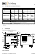
10.2 OPTIONS FOR BASIC COOLER ECM-EXII Heat exchanger type Part No Material of heat exchanger Max. gas flow rate Sample gas pressure abs. Sample gas connection Condensate connection P at max. flow Stagnant space approx. Peristaltic pump SR25.2 ECM-1G 93K0140 Borosilicate glass 250Nl/h max. 2bar (3bar)1 GL18 for Ø6mm a.d. tube* GL25 for Ø12mm tube* Ø8mm or Ø10mm** 1mbar 100ml ECM-1PV 93K0170 PVDF ECM-1SS 93K0160 st. steel 316Ti 250Nl/h max. 10bar 250Nl/h max.
The cooler ECM-ExII is equally suitable for wall installation. The depth of the housing of the cooler is 270mm (316mm with optional mounted peristaltic pumps ). WARNING! The cooler ECM-ExII corresponds to the system protection IP20 (EN 60529) and therefore suitable for use in clean and dry rooms. Solids and water must be avoided to enter the cooler housing via the ventilation outlet. For installation according to NEC article 501.
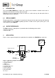
Sample OUT Sample IN Cooling block +5°C Condensate OUT Figure 3 Schematic diagram of the heat exchanger function 13 RECEPTION AND STORAGE The ECM-ExII gas cooler is a complete pre-installed unit.
14 INSTALLATION INSTRUCTIONS The ECM-ExII cooler is suitable for wall mounting. NOTE! The cooler is only suitable for dry and clean rooms (IP20). The operating position for this cooler is exclusively vertical. This is the only way to ensure proper separation and removal of condensate in the heat exchangers.
NOTE! Do not mix up the hose connections; the inlet and outlet connections of the heat exchangers are marked with arrows; Ensure that the connections are sealed adequately; To ensure free removal of the condensate, ensure that the listed diameters for the condensate removal lines are not reduced! Ensure that the connections are sealed adequately by noting the following: Borosilicate glass heat exchangers with connections GL18-6 respectively GL25-12 (standard) Before assembly, check the GL coupling
15.2 ELECTRICAL CONNECTIONS CARE! When connecting the equipment, please ensure that the supply voltage is identical with the information provided on the model type plate! WARNING! NOTE! WARNING! Do not work at alive parts unless the area is known to be nonhazardous. Attention must be paid to the requirements of IEC 364 (DIN VDE 0100) when setting high-power electrical units with nominal voltages of up to 1000V, together with the associated standards and stipulations.
Figure 5 Electrical sockets alarm contact The connection of the mains respectively status alarm signals happens as follows: 16 release the screws (7 pcs.) from the cooler top and remove it; put the cables (6-12mm) through one of the cable glands and connect them according to a.m. wiring plan; the re-installation of the cooler top happens in the opposite way. START-UP The thermo-hydraulic controlled cooling system of the ECMExII permit automatic start-up of the cooler.
17 CLOSING DOWN NOTE! CARE! 18 The location for the cooler must remain frost-free, even when the unit has been switched off! If the cooler unit is putting out of action for a short time no particular measures need to be taken. We recommend sweeping the cooler with inert gas or ambient air while the unit is putting out of action for a longer time. Aggressive condensate is possible.
Replace the heat exchangers as follows: Dry and clean the push-in opening in the aluminium cooling block with a cloth; Smear the push-in opening with a thin and equal layer of thermal conductivity paste (part no. 90K0115); Smear the heat exchangers with a thin and equal layer over the whole surface with thermal conductivity paste (part no. 90K0115) to ensure good conduction of heat.
18.3 MAINTENANCE OF THE OPTIONAL MOUNTED PERISTALTIC PUMP(S), TYPE SR25.2 Before the maintenance work is carried out, it is necessary hat the specific safety procedures pertaining to the system and operational process are observed! DANGER Dangerous voltage! It is necessary to take the pump off the mains before any assembly, maintenance and repair work is carried out! Flexible tube, conveying belt, contact pulleys and contact springs are the only parts of the pump subject to wear.
Take away conveying belt and remove the old hose set from the guides by the hose connectors; Press the two contact pulleys and check whether the spring pressure is still sufficient, if not, the contact springs have to be changed; Put the new hose set with the hose connectors into the guides of the conveying belt ; NOTE! Only the usage of the original hose set guarantees a perfect function. Never lubricate the hose.
19 OPERATING OF THE BUILT-IN ELECTRONIC TEMPERATURE CONTROLLER Only use temperature controller 01 B 8365. NOTE! In normal operation the display of the temperature controller shows the actual cooling temperature. Figure 7 shows the front view of the temperature controller. Figure 7 Front view of the temperature controller 19.1 CHANGING THE SET VALUE To change the set value the P-key has to be pushed < 2 sec. The company fixed value of 5°C appears. With the two arrow keys the value can be changed.
20 TROUBLE SHOOTING The following table should give an overview of possible errors and an instruction to check and to repair them (is not valid for the starting-up period of cooler).
21 SPARE PARTS LIST Wear, tear and replacement part requirements depend on specific operating conditions. The recommended quantities are based on experience and they are not binding. Electric gas cooler ECM-ExII (C) Consumable parts (R) Recommended spare parts (S) Spare parts Part No.
22 APPENDIX Sample output dew point depending on gas flow rate at sample inlet dew points of 60C Circuit diagram ECM-ExII Drawing No.: 2456-5.01.0 Ex-certifikates: ATEX, CSA, FM Further product documentation can be seen and downloaded from our home page: www.mc-techgroup.com Threaded couplings for ”GL” glass connections Document: 3-5.1.1 Instruction manual peristaltic pump SR25.1 Document: 3-7.1ME Automatic liquid drain AD-SS Document: 3-6.2.
Figure 9 Circuit diagram ECM-ExII Gas sampling and gas conditioning technology 3-3.
Gas sampling and gas conditioning technology 3-3.
Gas sampling and gas conditioning technology 3-3.
Gas sampling and gas conditioning technology 3-3.
Gas sampling and gas conditioning technology 3-3.
Gas sampling and gas conditioning technology 3-3.
Gas sampling and gas conditioning technology 3-3.
Gas sampling and gas conditioning technology 3-3.
Gas sampling and gas conditioning technology 3-3.
Gas sampling and gas conditioning technology 3-3.
Gas sampling and gas conditioning technology 3-3.
Gas sampling and gas conditioning technology 3-3.
Gas sampling and gas conditioning technology 3-3.
Gas sampling and gas conditioning technology 3-3.
Gas sampling and gas conditioning technology 3-3.