Operating Manual Electric gas cooler series EC® Version EC-L Gas sampling and gas conditioning technology 3-3.
Dear customer, we have made up this operating manual in such a way that all necessary information about the product can be found and understood quickly and easily. Should you still have any question, please do not hesitate to contact M&C directly or go through your appointed dealer. Respective contact addresses are to be found in the annexe to this operating manual. Please also contact our homepage www.mc-techgroup.com for further information about our products.
Content 1 2 3 4 5 6 General information ................................................................................................................... 4 Declaration of conformity ......................................................................................................... 4 Safety instructions ..................................................................................................................... 5 Warranty ...................................................................
Head Office M&C TechGroup Germany GmbH Rehhecke 79 40885 Ratingen Germany Telephone: 02102 / 935 - 0 Fax: 02102 / 935 - 111 E - mail: info@mc-techgroup.com www.mc-techgroup.com 1 GENERAL INFORMATION The product described in this operating manual has been examined before delivery and left our works in perfect condition related to safety regulations. In order to keep this condition and to guarantee a safe operation, it is important to heed the notes and prescriptions made in this operating manual.
3 SAFETY INSTRUCTIONS Please take care of the following basic safety procedures when mounting, starting up or operating this equipment: Read this operating manual before starting up and use of the equipment. The information and warnings given in this operating manual must be heeded. Any work on electrical equipment is only to be carried out by trained specialists as per the regulations currently in force.
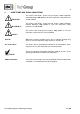
5 USED TERMS AND SIGNAL INDICATIONS DANGER! This means that death, severe physical injuries and/or important material damages will occur in case the respective safety measures are not fulfilled. WARNING! This means that death, severe physical injuries and/or important material damages may occur in case the respective safety measures are not fulfilled. This means that minor physical injuries may occur in case the respective safety measures are not fulfilled.
6 INTRODUCTION The patented M&C EC-L gas cooler unit is always to be installed in situations where there is interference from moisture in the gas to be measured. Reduction of the gas temperature inside the cooler to a stable and very low dew point effects a condensing-out of the sample gas. 6.1 SERIAL NUMBER The type plate with the serial number is located at the side panel of the cooler housing.
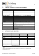
8 TECHNICAL DATA 8.1 FOR BASIC COOLER EC-L WITHOUT HEAT EXCHANGER Gas cooler series EC Part No. for basis cooler without heat exchanger, 230V 50Hz Part No.
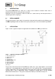
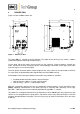
9 DESCRIPTION Figure 2 shows the EC-L cooler unit. 349 210 300 350 380 332 143 63 Figure 2 Dimensions EC-L The cooler EC-L is suitable for wall installation. The depth of the housing of the cooler is 300mm (349mm with optional mounted peristaltic pumps ). On the upper side of the cooler casing you will see the cutout for 2 heat exchangers. Sample gas enters and leaves the heat exchangers by the correspondingly connections on the upper part of the heat exchangers (see 8. technical data).
10 FUNCTION The M&C gas cooler type EC-L is a compressor cooler with status alarm capability. This ensures 100% availability of the cooler. Two Jet-stream heat exchangers made of Borosilicate glass, PVDF or stainless steel are located in a heat-insulated cooling block. All the heat exchangers are easily accessible and are arranged in such a way that they can be removed very simply.
12 INSTALLATION INSTRUCTIONS The EC-L cooler is suitable for wall mounting. NOTE! The operating position for this cooler is exclusively vertical. This is the only way to ensure proper separation and removal of condensate in the heat exchangers. During transport and installation, the cooler must always be stood up with the transport feet positioned underneath so that the oil in the closed compressor circuit cannot run out of the compressor case.
Correspondingly tube and hose connectors are optional available by M&C.
NOTE! WARNING! Attention must be paid to the requirements of IEC 364 (DIN VDE 0100) when setting high-power electrical units with nominal voltages of up to 1000V, together with the associated standards and stipulations. An external main switch must be provided. The main circuit must be equipped with a fuse of 10AT (over current protection); for electrical details see technical data (8.). Cooler versions with 115V resp. 120V have a built-in transformer to generate an internal current of 230V.
14 START-UP The thermo-hydraulic controlled cooling system of the EC-L permit automatic start-up of the cooler. The following description is valid for start-up of the gas cooler for an ambient temperature > 8°C. Before starting up the gas cooler, it must be placed in its operating position for at least two hours. The liquid inside the system may have been redistributed, and this could cause problems in operation.
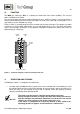
The EC-L cooler does not require any special maintenance intervals. The cooler is to be cleaned with compressed air according to the contamination level of the ambient air (see 16.2). 16.1 ADDING AND REPLACING THE HEAT EXCHANGERS Removal of the heat exchangers may be necessary to carry out maintenance or repair work.
16.3 MAINTENANCE OF THE OPTIONAL MOUNTED PERISTALTIC PUMPS, TYPE SR25.2 Before the maintenance work is carried out, it is necessary that the specific safety procedures pertaining to the system and operational process are observed ! DANGER Dangerous voltage ! It is necessary to take the pump off the mains before any assembly, maintenance and repair work is carried out ! Flexible tube, conveying belt, contact pulleys and contact springs are the only parts of the pump subject to wear.
Take away conveying belt and remove the old hose set from the guides by the hose connectors; Press the two contact pulleys and check whether the spring pressure is still sufficient, if not, the contact springs have to be changed; Put the new hose set with the hose connectors into the guides of the conveying belt ; NOTE! Only the usage of the original hose set guarantees a perfect function. Never lubricate the hose.
17 OPERATING OF THE BUILT-IN ELECTRONIC TEMPERATURE CONTROLLER In normal operation the display of the temperature controller shows the actual cooling temperature. Figure 7 shows the front view of the temperature controller. Figure 7 17.1 Front view of the temperature controller CHANGING THE SET VALUE To change the set value the P-key has to be pushed < 2 sec. The company fixed value of 5°C appears. With the two arrow keys the value can be changed.
18 TROUBLE SHOOTING The following table should give an overview of possible errors and an instruction to check and to repair them (is not valid for the starting-up period of cooler).
19 SPARE PARTS LIST Wear, tear and replacement part requirements depend on specific operating conditions. The recommended quantities are based on experience and they are not binding. Electric gas cooler EC-L (C) Consumable parts (R) Recommended spare parts (S) Spare parts Part No.
20 APPENDIX Sample outlet dew point depending on gas flow rate at sample inlet dew points of 80C Further product documentation can be seen and downloaded from our home page: www.mc-techgroup.com Threaded couplings for ”GL” glass connections Document: 3-5.1.1 Instruction manual peristaltic pump SR25.1 Document: 3-7.1ME Automatic liquid drain AD-SS Document: 3-6.2.3 Automatic liquid drain AD-P Document: 3-6.2.1 Condensate vessel TG, TK Document: 3-6.3.