
Owner manual

M&C TechGroup Germany GmbH • Rehhecke 79 • 40885 Ratingen • Germany
info@mc-techgroup.com • www.mc-techgroup.com • Fon +49 2102 935-0 • Fax +49 2102 935-111
6.4
Technical specications and illustrations are without
obligation, subject to modications. 10.08
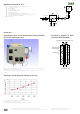
Dimensions in mm
Drawing shows EC-L with two heat exchangers out of glass, two pre-cooling stages, peristaltic pumps, a lter
with liquid alarm sensor and a diaphragm pump .
Heat exchanger(s), peristaltic pump(s), lter with liquid alarm sensor and diaphragm pump to be ordered
optionally!
Functioning diagram of M&C
Jet-Stream heat exchanger
Sample gas outlet dew point stability at gas inlet dew point of 80 °C.
Heat exchangers are connected in series.
Characteristics of heat exchanger out of PVDF or stainless steel on request.
Compact gas cooler EC-L with pre-cooler, filter, liquid alarm
sensor and diaphragm pump
Sample gas outlet dew point stability for EC-L-2G
M&C Jet-Stream
heat exchanger
Cooling block
Condensate - OUT
Sample gas - IN
Sample gas - OUT
+5°C
Application example for EC-L
1 Heated lter sample probe or dilution probe
2 Heated sample line
3 Cooler EC-L
4 3-way ball valve
5 Peristaltic pump SR25.2
6 Diaphragm pump
7 Fine lter FP-2T-D with liquid alarm LA1S
8 Aerosol lter CLF-5 /W optional according to application
9 Flow meter FM40, 25-250 Nl/hr
10 Analysers
8
5
condensate OUT
+5°C
4
3
10
9
7
EC-L
1 2
sample gas IN
test gas IN
6
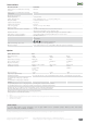
Dimensions