Operating Manual Electric gas cooler series EC® Version EC-EX (from model nos. 9904417) Gas sampling and gas conditioning technology 3-4.
Dear customer, we have made up this operating manual in such a way that all necessary information about the product can be found and understood quickly and easily. Should you still have any question, please do not hesitate to contact M&C directly or go through your appointed dealer. Respective contact addresses are to be found in the annexe to this operating manual. Please also contact our homepage www.mc-techgroup.com for further information about our products.
List of Contents 1 2 3 4 5 6 7 8 9 10 11 12 13 14 15 General information...................................................................................................................... 4 Declaration of conformity ............................................................................................................ 4 Electrical standards...................................................................................................................... 5 Safety instructions .................
Head Office M&C TechGroup Germany GmbH Rehhecke 79 40885 Ratingen Germany Telephone: 02102 / 935 - 0 Fax: 02102 / 935 - 111 E - mail: info@mc-techgroup.com www.mc-techgroup.com 1 GENERAL INFORMATION The product described in this operating manual has been examined before delivery and left our works in perfect condition related to safety regulations. In order to keep this condition and to guarantee a safe operation, it is important to heed the notes and prescriptions made in this operating manual.
3 ELECTRICAL STANDARDS The electrical standard of electrical equipment corresponds to the safety regulations concerning the EN61010, EN 50014 A1 to A5, EN 50016 A1, EN 50017 A1, EN 50018 A1 to A3, EN 50019 A1 to A3 and EN 50020 A1 to A2, for operating in hazardous areas Group II Category 2G. Attention must be paid to the certificate of conformity KEMA 03ATEX2113 (see appendix).
5 INFORMATION AND SAFETY INSTRUCTIONS FOR USING THE COOLER IN HAZARDOUS AREAS The compressor cooler EC-Ex is suitable for using in hazardous area category 2G. The explosion proof protection is: 230V / 115 : II 2 G EEx pedq [ib] IIC T4 (appr.-no.: 03 ATEX 2113) The certification of the cooler was done by the Kema the authorized institute of electrical equipment in the Netherlands. For detailed information and a copy of the certificate see appendix.
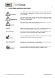
7 USED TERMS AND SIGNAL INDICATIONS DANGER! This means that death, severe physical injuries and/or important material damages will occur in case the respective safety measures are not fulfilled. WARNING! This means that death, severe physical injuries and/or important material damages may occur in case the respective safety measures are not fulfilled. This means that minor physical injuries may occur in case the respective safety measures are not fulfilled.
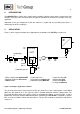
8 INTRODUCTION The M&C EC-EX gas cooler unit is always to be installed in situations where there is interference from moisture in the gas to be measured and if the point of installation is declared as hazardous area (see appendix). Reduction of the gas temperature inside the cooler to a stable and very low dew point effects a condensing-out of the sample gas. 9 APPLICATION Figure 1 shows a typical example of an application for installation of an EC-EX gas cooler unit.
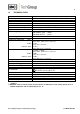
10 TECHNICAL DATA Sample outlet dew point Dew point stability Sample inlet temperature Sample inlet dew point Gas flow rate per heat exchanger Number of heat exchangers Material of heat exchangers Ambient temperature Admissible gas pressure range of adjustment: +2 °C ..... +7 °C, factory setting: +5 °C at constant conditions 0,25°C **Max. + 180°C **Max. +80°C **Max. 250l/h 1*, installation of max.
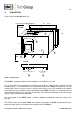
11 DESCRIPTION Figure 2 shows the EC-EX cooler unit . * necessary locating distance 465 84 TE 435 88 * 2HE 37,5 450 70 240 7 HE 4 85 235 5 6,2 310 °C> ON °C< 100 * 1 A 3 2 View A max. 4 X condensate out 6 2 X cable glands PG 13,5 7 Figure 2 EC-EX cooler The EC-EX is equally suitable for wall installation or mounting in a 19“ rack. The versions differ in the positioning of the LED function display .
The EC-EX cooling compressor has a special junction box and one surface area temperature alarm contact with manual reset button. The refrigeration circulation suction side of the EC-EX compressor has a pressure alarm unit with manual reset button. This alarms are connected into the Ex-i-circuit and to switch off the voltage of the compressor during compressor temperature alarm or pressure alarm. The manual Reset for the pressure alarm is cancelled since September 2004.
12 FUNCTION The M&C EC-EX gas cooler is a compressor cooler with status alarm capability. This ensures 100% availability of the cooler. Up to 4 Jet-stream heat exchangers made of Borosilicate glass, PVDF or stainless steel are located in a heat-insulated cooling block. All the heat exchangers are easily accessible and are arranged in such a way that they can be removed very simply. Figure 3 shows a schematic diagram of the functioning of the heat exchanger..
13 RECEPTION AND STORAGE The EC-EX gas cooler is a complete pre-installed unit.
15 SUPPLY CONNECTIONS 15.1 HOSE CONNECTIONS The hoses for the heat exchangers are laid out as per Figure 3.
15.2 ELECTRICAL CONNECTIONS WARNING! NOTE! When connecting the equipment, please ensure that the supply voltage is identical with the information provided on the model type plate. Attention must be paid to the requirements of IEC 364 (DIN VDE 0100) when setting high-power electrical units with nominal voltages of up to 1000 V, together with the associated standards and stipulations. Check the details on the type plate to ensure that the equipment is connected up to the correct mains voltage.
The power connection is in the terminal box inside the cooler housing Terminal 1 2 EC-EX Terminal box Connection L N 3 PE The potential-free contact of the status collector alarm is located as well in the terminal box inside the EC-EX cooler housing. Terminal 11 12 EC-EX Terminal box Connection NC COM 13 NO Two PG 13.5 cable glands are provided for the cable bushings through the base plate of the cooler casing.
16.1 FUNCTION SEQUENCE AND LED FUNCTION DISPLAY Three function display LED's are provided to give a visualization of the function sequence during startup of the cooler. According to the type of installation, they are located either on the front panel or the back panel of the cooler (Fig. 2). The top LED (red) indicates that the temperature set by the EC automatic control electronics has been exceeded or has not been reached.
17 CLOSING DOWN NOTE! The location for the cooler must remain frost-free, even when the unit has been switched off! If the cooler unit is putting out of action for a short time no particular measures need to be taken. We recommend sweeping the cooler with inert gas or ambient air while the unit is putting out of action for a longer time. WARNING! 18 Aggressive condensate is possible.
18.1 ADDING AND REPLACING THE HEAT EXCHANGERS Removal of the heat exchangers may be necessary to carry out maintenance or repair work.
19 TROUBLE SHOOTING Troubleshooting is made much easier by the LED function display. The following table shows possible reasons for error and how to correct them (not applicable for the running-up phase of the cooler).
LED display °C > red ON pink Function error and status alarm Equipment does not cool or cooling is insufficient; Probable cause Cooling compressor is not running; °C < (red LED V18 on control board is on) Checking / Correction 1. Check voltage in the EEx-d box at terminals X2.9 and X2.6 (N) (drive of the compressor starting coil). In case of 230V (115V) renew the EC-EX control board. There is no voltage at terminals X2.9 and X2.6 (N): 2.
20 EC AUTOMATIC CONTROL BOARD Figure 5 shows the arrangement of the EC-EX automatic control board (wiring scheme in Appendix). Figure 5 EC-EX automatic control board Gas sampling and gas conditioning technology 3-4.
20.1 TEMPERATURE SETTING FOR THE EC/ECS COOLER The EC-EX gas cooler is set at the factory to a regulated temperature of +5°C. Setting of the regulated temperature is done by trimming potentiometer P1, on the EC-EX automatic control board of the cooler. The setting range covers from 0°C to 20°C. Turning it to the left sets a lower temperature, and turning it to the right sets a higher temperature.
21 CHECKING THE TEMPERATURE SENSOR The temperature sensor of the EC-EX cooler is a KTY-semiconductor. Figure 7 Temperature sensor resistance Gas sampling and gas conditioning technology 3-4.
22 SPARE PARTS LIST Wear, tear and replacement part requirements depend on specific operating conditions. The recommended quantities are based on experience and are not binding.
23 APPENDIX Sample output dew point (ambient temperature 20°C) depending on gas flow rate Circuit diagram EC-EX automatic control board 230V, drawing number : 2392 - 5.04.0; Circuit diagram EC-EX automatic control board 115V, drawing number : 2392 - 5.05.0; Certificate KEMA 03ATEX2113 More product documentation is available on our Internet catalogue: www.mc-techgroup.com. Instruction manual peristaltic pump SR 25.1, Document : 3-7.1-MD; Condensate vessel TG, TK Document : 3-6.3.
Sample outlet dew point (ambient temperature 20°C) depending on gas flow rate Sample input dew point Gasausgangs-Taupunkt Sample outlet dewpoint 60°C 40°C °C 10 EC-G 5 N l/h 62,5 Messgas-Durchfluss 125 187,5 Gas flow rate 250 Gasausgangs-Taupunkt Sample outlet dewpoint °C 10 EC-SS 5 N l/h 62,5 Messgas-Durchfluss 125 187,5 250 Gas flow rate Gasausgangs-Taupunkt Sample outlet dewpoint °C 10 EC-PV 5 N l/h 62,5 Messgas-Durchfluss 125 187,5 250 Gas flow rate Figure 8 Sample outlet d
Schematic description of the EC-EX cooler including installation position of sensors Compression contact Temperature sensor Temperature contact Figure 9 Schematic drawing Gas sampling and gas conditioning technology 3-4.
Figure 10 Circuit diagram EC-EX 230V/50Hz Gas sampling and gas conditioning technology 3-4.
Figure 11 Circuit diagram EC-EX 115V/50-60Hz Gas sampling and gas conditioning technology 3-4.
Gas sampling and gas conditioning technology 3-4.
Gas sampling and gas conditioning technology 3-4.
Gas sampling and gas conditioning technology 3-4.