
Operator's manual User Manual

31
Gas sampling and gas conditioning technology 3-4.20-ME
20 EC CONTROL BOARD
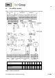
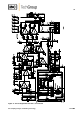
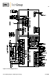
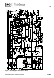
Figure 15 shows the layout of the EC30 control board (wiring diagram in appendix).
Figure 15 EC30 control board
Temperature
adjustment
(zero)
Alarm threshold
(<-25°C at MP3)
Power
Trans-
former
Solenoid
valve
Power
supply
Channel 2
Channel 1
Channel
Operating indication
Heating
Operation
Test
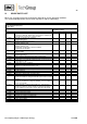
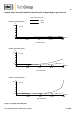
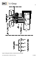
Voltage at MP1, MP2, MP3 measured
against MP5 (V):
1
2
3
4
5
6
7
8
Corresponding temperatures in °C
+30
+20
+10
0
-10
-20
-30
-40
Voltage at MP1, MP2, MP3 measured
against MP5 (V):
1
2
3
4
5
6
7
8
Corresponding temperatures in °C
+30
+20
+10
0
-10
-20
-30
-40