Operating Manual Low-temperature electric gas cooler series EC® version EC30 and EC-30/FD Gas sampling and gas conditioning technology 3-4.
Content 1 2 3 4 5 6 General information ...................................................................................................................5 Declaration of conformity ..........................................................................................................5 Safety instructions .....................................................................................................................6 Warranty .....................................................................
List of Illustrations Figure 1 Figure 2 Figure 3 Figure 4 Figure 5 Figure 6 Figure 7 Figure 8 Figure 9 Figure 10 Figure 11 Figure 12 Figure 13 Figure 14 Figure 15 Figure 17 Figure 18 Figure 19 Figure 20 Figure 21 Example of application of EC-30/FD .................................................................................. 9 EC-30 with options EC-F and EC-FD .............................................................................. 11 Schematic diagram of functioning of heat exchanger ........
Dear customer, we have made up this operating manual in such a way that all necessary information about the product can be found and understood quickly and easily. Should you still have any question, please do not hesitate to contact M&C directly or go through your appointed dealer. Respective contact addresses are to be found in the annexe to this operating manual. Please also contact our homepage www.mc-techgroup.com for further information about our products.
Head Office M&C TechGroup Germany GmbH Rehhecke 79 40885 Ratingen Germany Telephone: 02102 / 935 - 0 Fax: 02102 / 935 - 111 E - mail: info@mc-techgroup.com www.mc-techgroup.com 1 GENERAL INFORMATION The product described in this operating manual has been examined before delivery and left our works in perfect condition related to safety regulations. In order to keep this condition and to guarantee a safe operation, it is important to heed the notes and prescriptions made in this operating manual.
3 SAFETY INSTRUCTIONS Please take care of the following basic safety procedures when mounting, starting up or operating this equipment: Read this operating manual before starting up and use of the equipment. The information and warnings given in this operating manual must be heeded. Any work on electrical equipment is only to be carried out by trained specialists as per the regulations currently in force.
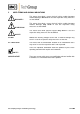
5 USED TERMS AND SIGNAL INDICATIONS DANGER! This means that death, severe physical injuries and/or important material damages will occur in case the respective safety measures are not fulfilled. WARNING! This means that death, severe physical injuries and/or important material damages may occur in case the respective safety measures are not fulfilled. This means that minor physical injuries may occur in case the respective safety measures are not fulfilled.
6 INTRODUCTION The patented M&C EC30 gas cooler with universal unit EC-F and EC-30/FD with unit EC-FD is always to be installed in situations where there is interference from moisture in the gas to be measured, or if the measured components exhibit very high sensitivity to water vapour or if long and expensive heated sampling lines are to be avoided. Reduction of the gas temperature inside the cooler to a stable and very low dew point effects a condensing out of the sample gas.
7 APPLICATION The patented M&C ultra-low temperature cooler EC-30(/FD) finds its applications in the analytical field for reducing the dew point of humid sample gases, providing a stable and very low dew point and reducing aerosol formation in the analyser. By mounting the cooler near to the sample point, costly energy consuming heated sample lines can be avoided. An extremely stable and low gas dew point avoids water vapour cross-sensitivity and volumetric errors.
8 TECHNICAL DATA Cooler series EC® Part No. With integrated universal unit: Version EC-30 02K6000 (a)** EC-F to force the ventilation Gas connection Condensate connections tube connector DN 4/6 i./o. d. mm 3x tube connector GL25-12 mm 1x tube connector DN 4/6 i./o. d. mm Duran glass, PTFE, PVDF Duran glass, PTFE, PVDF, Novoprene 90 Nl/hr-250 Nl/hr* max. 3 bar abs. max. 2 bar abs. +5 to +45 °C -20 to +60°C -30 °C max. 180 °C* max. 80 °C* max. 860 kJ/hr* 230V 50Hz 380VA or **Part No. ...
9.1 ASSEMBLY Figure 2 EC-30 with options EC-F and EC-FD Gas sampling and gas conditioning technology 3-4.
The EC30 is equally suitable for wall installation or mounting in a 19” rack. The versions differ in the positioning of the LED function display . While for wall installation the LED function display can be fitted into the corresponding cut-outs in the EC30 front panel, for 19” rack mounting this is done using the cut-outs in the back panel of the casing. This positioning is done at the factory when stating the type of installation of the EC30 gas cooler.
A decoupled compressor cooler system has a heat-insulated cooling block at a constant temperature of +1C. Control of the compressor is contactless done by the EC automatic control electronics and is therefore not subject to wear. The pre-cooling stage ensures that the greater part of the condensate has already been removed from the gas stream. The low-temperature stages are provided with two modified jet stream EC30 heat exchangers made of Duran glass.
The heat energy from the cooling system is drawn off by the forced ventilated condenser. The LED function display on the front of the cooler shows the operating status. Alarm warnings for over- and under-temperature are given as a collective status alarm via a relais output with two potential-free changeover contacts. 11 RECEPTION AND STORAGE The EC-30(/FD) gas cooler is a complete pre-installed unit.
12 INSTALLATION INSTRUCTIONS The EC-30(/FD) cooler is equally suitable for wall mounting or for installation in a 19" rack. Please state the desired type of mounting when ordering, so that the LED function display can be positioned to match at the factory! NOTE! NOTE! The operating position for this cooler is exclusively vertical. This is the only way to ensure proper separation and removal of condensate in the heat exchangers.
When fixing the connectors in the PVDF heat exchanger hold up with a wrench at the pane of the bolt head! The connection for the gas inlet (see above) is made to the heat exchanger of the pre-cooling stage 3(fig. 2). This is marked accordingly with an arrow. The outlet for gas to be measured, DN 4/6, is located as standard on the universal unit EC-F located on the underside of the cooler casing (fig. 2).
Figure 6 shows the location of the terminal X0 behind the front panel of the EC-30 casing (fig. 2).
14 START-UP The control electronics of the EC30(/FD) permit automatic start up of the cooler, which also ensures safe and guaranteed operation regardless of external influences such as a power failure. The error diagnostics guarantee full monitoring and reporting of possible sources of error. The following description is valid for startup of the gas cooler for an ambient temperature > 5C. Before starting up the gas cooler, it must be placed in its operating position for at least two hours.
Switching on the low-temperature stages After approx. 30 minutes the pre-cooler stage has been cooled down to a temperature below +4C. The top red LED goes out and the bottom red LED lights up. The low-temperature stage is activated and starts operating at full power. The cooler compressor is switched of as soon as the pre-cooler stage reaches the controlled temperature of +1C. The middle LED lights up green.
15 CLOSING DOWN NOTE! The location for the cooler must remain frost-free, even when the unit has been switched off! If the cooler unit is put out of operation for a short time no particular measures have to be taken. We recommend purging the cooler with inert gas or ambient air, while the unit is put out of operation for a longer time. WARNING! 16 Aggressive condensate is possible.
16.1 MAINTENANCE OF THE PERISTALTIC PUMPS TYPE SR25.1 OF THE EC-30/FD Before the maintenance work is carried out, it is necessary that the specific safety procedures pertaining to the system and operational process are observed! DANGER Dangerous voltage! It is necessary to take the pump off the mains before any assembly, maintenance and repair work is carried out! Flexible tube, conveying belt, contact pulleys and contact springs are the only parts of the pump subject to wear.
Take away conveying belt and remove the old hose set from the guides by the hose connectors; Press the two contact pulleys and check whether the spring pressure is still sufficient, if not, the contact springs have to be changed; Put the new hose set with the hose connectors into the guides of the conveying belt ; NOTE! Only the usage of the original hose set guarantees a perfect function. Never lubricate the hose.
16.2 REPLACING THE HEAT EXCHANGERS Removal of the heat exchangers may be necessary to carry out maintenance or repair work. It is possible to replace the heat exchanger (pre-cooling stage) without switching off the entire cooler. This does not apply to the heat exchangers of the low-temperature stages and . Icing-up at operating temperatures of -30C will make it impossible to dismantle the unit. It will take approximately two hours to defrost after switching off the cooler.
17 TROUBLE SHOOTING Troubleshooting is made much easier by the LED function display. The following table shows possible reasons for error and how to correct them (not applicable for the running-up phase of the cooler).
LED display Function error and status alarm Equipment does not cool; Probable cause Checking / Correction Ambient temperature < -2°C Ambient temperature must be ≥ +5°C! °C > ON green °C < red Cooler has been Cooling compressor Check temperature at EC automatic control board over-cooled (temp. stopped; (18.2); < - 2°C); If temperature < -2°C (< -0,2V): Check PT100 temperature sensor (19.1); If not OK: Replace sensor.
18 EC AUTOMATIC CONTROL BOARD Figure 7 shows the arrangement of the EC automatic control board of the pre-cooling stage (wiring scheme in Appendix). Figure 9 EC automatic control board Gas sampling and gas conditioning technology 3-4.
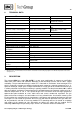
18.1 CONNECTING THE COOLING COMPRESSOR The cooling compressor is connected to the EC automatic control board (Fig. 9). Figure 10 shows the connection diagram for the compressor. cable Nr.1 from EC automatic control board pin 21 cable Nr.2 from EC automatic control board pin 24 cable Nr.3 from EC automatic control board pin 22 PE green/yellow from EC automatic control board pin 23 Condenser Connection cable Part No.: KL0001 cable No.1 230V 80uF Part No.
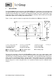
18.2 TEMPERATURE SETTING FOR THE COOLER The pre-cooling stage is set at the factory to a regulated temperature of +1°C. R Uref P3 + Current-Temp. Utemp Ri > 100k - °C Uref C9 Setting-Temp. Connect a d.c. voltmeter to terminals 1, 2 and 3! Figure 11 Temperature adjustment Setting of the regulated temperature is done by trimming potentiometer P3, on the EC automatic control board of the cooler. The setting range covers temperatures from 0°C to 20°C.
Figure 12 shows the voltage characteristics in relation to temperature. If the measured voltage is inside the shaded area, the sensor is defective and has to be replaced. 4 3 2 1 V 0 -1 -2 -3 -30 -20 -10 0 10 20 30 40 °C Figure 12 Voltage in relation to the temperature of the cooling stage Resistance method In this case the sensor must be disconnected from pins 1 and 2 at the EC automatic control board (Fig. 9) and removed from the cooling block.
Figure 14 Sensor voltage as function of temperature If the measured voltage is inside the shaded area, the sensor is defective and has to be replaced. Gas sampling and gas conditioning technology 3-4.
20 EC CONTROL BOARD Figure 15 shows the layout of the EC30 control board (wiring diagram in appendix).
20.1 FUNCTION SEQUENCE OF THE EC30 CONTROL ELECTRONICS Nine LEDs are available for error diagnosis of the EC30 control electronics to display all the logic and alarm functions. NOTE! Do not change any settings that had been made at the factory! With the potentiometer P1 the temperature (zero point) is adjusted (measuring points M1, M2) Potentiometer P2 figures the alarm < -25°C (measuring point M3).
The sample gas flows through the pre-cooling stage and low-temperature stage . This cycle will be changed automatically every three hours. In the event of a brief (mains) power failure: The current cycle status will be stored; All LEDs go out; The status alarm contact is activated; The flow of sample gas is cut off externally, in case the sample gas pump or a solenoid valve in the sample gas line are to be controlled by an alarm contact.
21 SPARE PARTS LIST Wear, tear and replacement part requirements depend on specific operating conditions. The recommended quantities are based on experience and are not binding. Gas cooler EC-30(/FD) (C) Consumable parts (R) Recommended spare parts (S) Spare parts Part No.
22 APPENDIX Sample outlet dew point (ambient temperature 20°C) depending on heat exchanger material, inlet dew point and gas flow rate Circuit diagram EC automatic control board, drawing number : 2300 - 5.04.2 Circuit diagram EC30 (from 9/98), drawing number: 2389 - 5.01.3 Circuit diagram EC-30-control electronic, drawing number: 2389 - 5.02.3 Wiring plan automatic condensate removal unit EC-FD, drawing number : 2300-5.05.
Sample outlet dew point (ambient temperature 20°C) depending on gas flow rate sample inlet dew point 60°C Sample outlet dew point 40°C °C 10 EC-G 5 N l/hr 62,5 125 187,5 250 Gas flow rate Sample outlet dew point °C 10 EC-SS 5 62,5 125 187,5 N l/hr 250 Gas flow rate Sample outlet dew point °C 10 EC-PV 5 N l/hr 62,5 125 187,5 250 Gas flow rate Figure 16 Sample outlet dew point Gas sampling and gas conditioning technology 3-4.
Figure 17 Circuit diagram EC automatic control board Gas sampling and gas conditioning technology 3-4.
Figure 18 Circuit Diagram EC-30 Gas sampling and gas conditioning technology 3-4.
Figure 19 Circuit diagram control electronic EC-30 Gas sampling and gas conditioning technology 3-4.
Figure 20 Wiring plan automatic condensate removal unit EC-FD Gas sampling and gas conditioning technology 3-4.