Operating Manual Gas Dilution Unit Versions DIL-1, DIL-1/H Gas sampling and gas conditioning technology 2-1.1.7.
Dear customer, we have made up this operating manual in such a way that all necessary information about the product can be found and understood quickly and easily. Should you still have any question, please do not hesitate to contact M&C directly or go through your appointed dealer. Respective contact addresses are to be found in the annexe to this operating manual. Please also contact our homepage www.mc-techgroup.com for further information about our products.
Contents 1 2 3 4 5 6 7 General information...................................................................................................................... 5 declaration of conformity............................................................................................................. 5 Safety instructions ....................................................................................................................... 6 Warranty .........................................................
List of Illustrations Figure 1 Figure 2 Figure 3 Figure 4 Figure 5 Figure 6 Figure 7 Figure 8 Figure 9 Figure 10 Figure 11 Figure 12 Figure 13 Figure 14 Figure 15 Dilution unit DIL-1 ............................................................................................................... 8 Dilution unit DIL-1/H ............................................................................................................ 9 Gas flow scheme DIL-1 with possible options ..................................
Head Office M&C TechGroup Germany GmbH Rehhecke 79 40885 Ratingen Germany Telephone: 02102 / 935 - 0 Fax: 02102 / 935 - 111 E - mail: info@mc-techgroup.com www.mc-techgroup.com 1 GENERAL INFORMATION The product described in this operating manual has been examined before delivery and left our works in perfect condition related to safety regulations. In order to keep this condition and to guarantee a safe operation, it is important to heed the notes and prescriptions made in this operating manual.
3 SAFETY INSTRUCTIONS Please take care of the following basic safety procedures when mounting, starting up or operating this equipment: Read this operating manual before starting up and use of the equipment. The information and warnings given in this operating manual must be heeded. Any work on electrical equipment is only to be carried out by trained specialists as per the regulations currently in force.
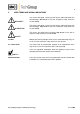
5 USED TERMS AND SIGNAL INDICATIONS DANGER! This means that death, severe physical injuries and/or important material damages will occur in case the respective safety measures are not fulfilled. WARNING! This means that death, severe physical injuries and/or important material damages may occur in case the respective safety measures are not fulfilled. This means that minor physical injuries may occur in case the respective safety measures are not fulfilled.
6 INTRODUCTION The non-heated or electrically heated M&C dilution unit DIL-1 /(H) is used in the analysis technique whereever the measuring method or the handling of the process gas requires a dilution of the sample gas or the components to be measured. Examples are the measurement of extremely toxic gases, the determination of the gas moisture or emission measurement.
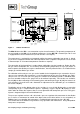
104 450 430 To>+30°C Reset Tsoll 0-180°C Option I Bypass out* (undiluted) Tu<-30°C PG 13,5 300 Alarm-Kontakt Temp.-min 280 Netz 230V,50Hz (115V,60Hz) Option II Sample out* (undiluted) Ø6 * Connection tube 6x1mm ** Connection tube 8x1mm Figure 2 Sample in* (non diluted) Testgas in* Bypassgas in* Sample out** (non diluted) Depressionmanometer* Dilution gas in* Dilution unit DIL-1/H The M&C dilution units DIL-... are mounted on a plate for wall mounting.
7.1 VARIATIONS The two basic versions DIL-1 and DIL-1/H can be extended by several options. Option I Includes a bypass for dilution gas with bypass injector for a fast suction of sample gas in order to shorten for example the response time in case of high dilution ratios. Option II Includes an additional sample gas outlet „non-diluted“. Option –A Includes a pressure regulator with manometer and a manometer for control of the low pressure on the critical orifice.
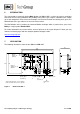
Test gas Option I Dilution gas Bypass 0-6bar * ** * 0-6bar ** -1-0bar ** Sample in Sample out Bypass-out Undiluted (Option II Sample out diluted ) ** Components for version/control panel -A or -S * Additional components for -A or -S for version/control panel -A1 or -S1 Figure 3 Gas flow scheme DIL-1 with possible options Test gas Option I Bypass 0-6bar * Dilution gas 0-6bar * ** ** -1-0bar ** Sample in 180°C Bypass out Sample out undiluted (Option II ) Sample out undiluted **
104 450 430 To>+30°C Reset Tsoll 0-180°C Option I Bypass out* (undiluted) Tu<-30°C PG 13,5 8 7 6 5 4 3 2 1 300 Alarm-Kontakt Temp.
8 TECHNICAL DATA Dilution ratios of the critical orifices „a“ to „g“ a 500 b 200 c 100 d 50 e 30* f 20 g 10:1 Sample flow rate with critical orifices „a“ to „g“ 1,4 2,7 5,5 11 19* 28 55l/h1) Possibility to adapt the dilution factor With dilution gas pressure adjustment -5% to +30%2) Dilution gas flow rate with injector version I or II I: 480 - 600 Nl/h, optional II: 1800 – 3000 Nl/h Dilution gas pressure on inlet of pressure controller Min. 4,5 bar, max.
9 DILUTION PRINCIPLE The functional principle of the dilution unit is based on ultrasonic flow through a critical orifice (see Fig. 4). The flow through the orifice is constant when the differential pressure via the orifice is higher than 500 mbar. For the atmospheric inlet pressure (Pin = 1020 mbar), this means a pressure at the orifice outlet (Pout) of less than 520 mbar absolute. The necessary vacuum at the orifice outlet is produced by an injector operated with dilution gas.
10 DIMENSIONS The following illustration shows the dimensions of the dilution units DIL-1 and DIL-1/H. DIL-1: 95 300 280 205 180 Ø6 DIL-1 with /A or /A1: 450 430 250 155 95 230 Ø6 Gas sampling and gas conditioning technology 2-1.1.7.
DIL-1/H: 104 450 430 To>+30°C Reset Tsoll 0-180°C Tu<-30°C PG 13,5 300 280 Ø6 DIL-1/H with /A or /A1 : 500 480 104 To>+30°C Reset Tsoll 0-180? C Tu<-30°C PG 13,5 370 350 Ø6 Gas sampling and gas conditioning technology 2-1.1.7.
Option control panel –S or -S1: 482 (84TE) Option: Bypass Steuerpanel Bypass-Injector Beipass-Injektor Dilution gas Verdünnungsgas Test gas Prüfgas Open Auf 2,0 132 (3HE) 1,0 0,0 Figure 8 Injector-vacuum Injektor-Unterdruck Open Auf 3,0 3,0 2,0 4,0 5,0 1,0 6,0 0,0 -0,6 -0,4 4,0 -0,8 5,0 6,0 -1,0 -0,2 0,0 Dimensions (mm) dilution units DIL–1.. and control panel –S or –S1 Sample gas IN Back pressure max. 1,2 bar abs.
11 RECEIPT AND STORAGE Carefully remove the dilution unit and any accessories from the transport packaging immediately after receipt and check the completeness of the delivery against the packing list. Check the goods for possible transport damages and, if necessary, notify immediately your transport insurer of any damage.
The connections for the supply and sample lines are as follows: Connection Sample In (undiluted) Testgas in Dilution gas In Low pressure manometer Sample gas Out (diluted) Option I: Bypass gas In Bypass gas Out (diluted) Option II: Sample gas Out (undiluted) 13.
13.3 CONNECTION OF DILUTION GAS OR BYPASS GAS For connection of the supply lines, tube connectors with dimension 6 x 1mm are available. mm zur Verfügung. The connection fittings of the heated dilution units are located outside the cover and can be connected without disassembly. Only when using the heated versions and option I, a heated “undiluted” sample line is connected to the bypass outlet.
NOTE! For the erection of power installations with nominal voltages of up to 1000V, the requirements of VDE 0100 and its associated standards and specifications must be observed. A main switch must be provided externally. The supply circuit of the unit must be equipped with a fuse with the correct rating (over current protection); the electrical details see technical data. Remove cover of the connection box. Insert the mains cable (min.
14 INITIAL STARTING Prior to initial use, system and process-specific safety measures must be observed. The relevant safety requirements and procedures for the medium to be sampled must be heeded. WARNING! The supply of gas to the injectors is only allowed when the heated dilution unit has reached its operating temperature (see technical data).
Injektortyp Injector type Injektor-Nr. I Injector No. Betriebsdruck Operating pressure [bar] 2,4 2,6 2,8 3,0 3,2 3,4 3,6 3,8 4,0 689 Durchfluss Flow [l/h] Für Verdünnungssystem-Nr. For dilution system No.
14.1 CALIBRATION A calibration of the downstream analyser system or checking the dilution factor must always be effected under operation conditions. Above the test gas valve, an appropriate test gas can be feeded. WARNING! The gas pressure must be above 0,7 bar, because the pressure control valve installed has an opening pressure of 0, 7 bar. When using the control panel, the respective ball valve for the test gas supply must be opened and the flow rate be set on the flowmeter.
16 MAINTENANCE Prior to any maintenance of repairing works, system and process specific safety measures must be observed. Agressive condensate possible. Wear safety glasses and appropriate protective clothing! WARNING! Do not touch the surface of the dilution unit during operation as this can cause burns due to the high surface temperatures. Wear protective gloves.
16.1 DISASSEMBLY OF THE CROSSPIECE For disassembling of the crosspiece, the heating of the heated dilution unit should be switched off so that the unit can cool down. Figure 13 shows the explosion drawing of the dilution crosspiece. Figure 13 Explosion drawing of the dilution crosspiece We recommend to proceed according to the following steps: Remove the insulation cover of the dilution unit, if applicable; Remove all tube connectors on the dilution crosspiece.
16.2 CLEANING OF THE CRITICAL ORIFICE AND CHECK OR CHANGE OF THE ORINGS Do not clean the critical orifice mechanically. Cleaning should be effected in an ultrasonic bath ! WARNING! Figure 13 shows the position of the orifice in the crosspiece and the O-ring seals.
16.3 CHANGE AND CLEANING OF THE INJECTION NOZZLE NOTE! For cleaning the injector, it is not necessary to remove the nozzle out of the crosspiece. The nozzle can be cleaned together with the complete crosspiece in an ultrasonic bath.
NOTE! 17 For cleaning the injection nozzle, you need not necessarily pull the nozzle out of the T-piece. The nozzle can be cleaned together with the complete Tpiece in an ultrasonic bath. If you blow through the nozzle, this must be done from the jet pipe side. SPARE PARTS LIST The wear, tear and spare part requirements depend on the specific operating conditions.