
User Manual

Gas sampling and gas conditioning technology 5-1.10.7-ME
M&C TechGroup Germany GmbH z Rehhecke 79 z 40885 Ratingen z Germany z Tel.: (0)2102/935-0 z Fax: (0)2102/935-111 z www.mc-techgroup.com
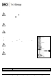
Glass frit
Filter element holder
Surface
Plain washer
Press screw
Part No.:90F3515
Part No .:90F 35 00
Part No.:90F3520
Part No.:90F3505
Part No.:90F3525
Part No .:90F 35 10
Diaphragm filter
Part No.:91E4010
O-ring
O-ring
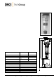
Connection of the sample line
The connections of the sample lines are marked by red arrows.
When using the upper entry d on the head of the filter for the measuring gas inlet resp. outlet, the
function of the filter is not guarantied (see flow direction in the filter).
Mounting Instruction Water-Stop CLF-5/W
The following instruction shows the mounting of the PTFE diaphragm into the liquid particle filter type CLF-5/W.
The system must be checked directly when flow is interrupted. A water breakthrough can damage
the analyser(s). Pay attention to absolutely cleanness when mounting the diaphragm.
Contaminations affect the func tion of the Water-Stop.
The maximum working pressure is 2bar absolute and the maximum temperature is +80°C.
Aggressive condensate possible. Wear safety glasses and protective clothes!
The following steps have to be carried out:
• Unscrew the f ilter glass count e r-clockwis e.
• Unscrew the filter element holder d.
• Unlock the press screw h and dismantle the glass frit c with the
diaphragm filter e and the flat ring disc f.
When re-fitting the glass frit be sure that the smooth side is opposite
to the filter element holder.
• Fit the diaphragm filter with the weft side towards the glass frit.
• Place the flat ring disc on the diaphragm filter.
When changing the O-ring of the press screw do not roll up. In case
other materials for the O-ring have been used due to technical
reasons, this is noted on the type plate. Please pay attention to this
and specify when ordering replacement par ts.
Screw the press screw by hand into the filter element holder up to the diaphragm filter.
The assembly of the fluid particle filter happens in the oppo site way.
Recommended spare parts
Wear, tear and replacement part requirements depen d on specific operating conditions.
Part No. Description
90 F 3530 Spare part set consisting of: glass frit c, diaphra gm filter e, flat ring disc f and O-ri ng g
90 F 3535 Spare part set consisting of: diaphragm filter e, flat ring disc f