
Operator's manual


9
Gas sampling and conditioning technology 9-0.2-ME
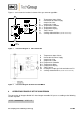
D
C
A
B
Y2
Y1
E1
°C
350
350
B 1.2
B 1.1
B 1.0
CG-2
CG-2M
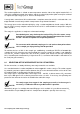
Figures 1 and 2 show the functional scheme of the gas converter type CG..
A Temperature Status Alarm
B Connection for Power Supply
C Sample Gas Inlet
D Sample Gas Outlet
B 1.0 Temperature Controller
B 1.1 Temperature Alarm
B 1.2 Temperature Display
E 1 Tube Furnace
Y 1 3/2-Way-Solenoid-Valve (not with version CG-2)
Y 2 3/2-Way-Solenoid-Valve (not with version CG-2)
Figure 1 Functional diagram of CG-2 and CG-2M
A Temperature Status Alarm
B Connection for Power Supply
C Sample Gas Inlet
D Sample Gas Outlet
B 1.0 Temperature Controller
B 1.1 Temperature Alarm
B 1.2 Temperature Display
E 1 Tube Furnace
E2 Heating bar sample gas inlet and outlet and Y1
Y 1 3/2-Way-Solenoid-Valve (not with version CG-2H-W)
Figure 2 Functional diagram CG-2H-W and CG-2MH-W
8 OPERATING PRINCIPLE OF THE CONVERSION
The conversion of nitrogen dioxide NO
2
into nitrogen monoxide NO passes according to the following
reaction equation:
2 NO
2
2 NO + O
2