
Operator's manual


4
Gas sampling and conditioning technology 9-0.2-ME
List of Illustrations
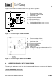
Figure 1 Functional diagram of CG-2 and CG-2M ............................................................................. 9
Figure 2 Functional diagram CG-2H-W and CG-2MH-W .................................................................... 9
Figure 3 Notch to differentiate the two cartridge types ...................................................................... 11
Figure 4 CG-2 and CG-2M ................................................................................................................ 14
Figure 5 CG-2H-W and CG-2MH-W ................................................................................................. 15
Figure 6 Pin configuration in the sub-D-plug X2 ............................................................................... 18
Figure 7 Catalyst life depending on the NO
2
concentration for varying flow rates and an Oxygen
concentration of 5 Vol.-% .................................................................................................... 21
Figure 8 Catalyst life depending on the NO
2
concentration for varying flow rates and an Oxygen
concentration of 10 Vol.-% .................................................................................................. 21
Figure 9 Catalyst life depending on the NO
2
concentration for varying flow rates and an Oxygen
concentration of 21 Vol.-% .................................................................................................. 21
Figure 10 Adapter for catalyst cartridge with handle ........................................................................... 23
Figure 11 Wiring plan CG-2M, Drawing No.: 2224-5.04.0 ................................................................. 30
Figure 12 Wiring plan CG-2H-W, Drawing No. : 2224-5.04.4 ........................................................... 31
Figure 13 Wiring plan CG-2MH-W, Drawing No. : 2224-5.04.5 ...................................................... 32