
Operator's manual

8
Gas sampling and conditioning technology 10-1.1-ME
7 FUNCTION
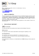
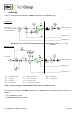
Figure 1 shows the function diagram of M&C combustion air conditioning units.
FI1 = Air filter
FI2 = Membrane dryer
FI3 = Catalyst
FI4 = Adsorber
M 1 = Compressor
P 1 = Manometer inlet
P 2 = Manometer outlet
S 3 = Pressure switch
Y1,2 = Solenoid valve
YA1 = Condensate separator
YD1 = Pressure controller
YD2 = Relief valve
YN1 = Needle valve
Figure 1 Function diagram of BA and BA-P4 combustion air conditioning units
The functional principle of the M&C combustion air conditioning unit is divided into two sections (see
Figure 1):
Gas conditioning section
Hydrocarbon elimination section
Gas conditioning Hydro Carbon
Removal
Connection for oil-
free compressed air
resp. instrument air
Air succing
Combustion air out
Combustion air out
Exhaust air out
Exhaust air out
Condensate out
Condensate out
Version BA
Version BA-P4