Instruction Manual Combustion Air Conditioning Unit Series BA Version BA, BA-P4 Gas sampling and conditioning technology 10-1.
Content 1 General information ................................................................................................................... 4 2 Declaration of conformity .......................................................................................................... 4 3 Safety instructions ..................................................................................................................... 5 4 Warranty .......................................................................
Dear customer, we have made up this operating manual in such a way that all necessary information about the product can be found and understood quickly and easily. Should you still have any question, please do not hesitate to contact M&C directly or go through your appointed dealer. Respective contact addresses are to be found in the annexe to this operating manual. Please also contact our homepage www.mc-techgroup.com for further information about our products.
Head Office M&C TechGroup Germany GmbH Rehhecke 79 40885 Ratingen Germany Telephone: 02102 / 935 - 0 Fax: 02102 / 935 - 111 E - mail: info@mc-techgroup.com www.mc-techgroup.com 1 GENERAL INFORMATION The product described in this operating manual has been examined before delivery and left our works in perfect condition related to safety regulations. In order to keep this condition and to guarantee a safe operation, it is important to heed the notes and prescriptions made in this operating manual.
3 SAFETY INSTRUCTIONS Please take care of the following basic safety procedures when mounting, starting up or operating this equipment: Read this operating manual before starting up and use of the equipment. The information and warnings given in this operating manual must be heeded. Any work on electrical equipment is only to be carried out by trained specialists as per the regulations currently in force.
5 USED TERMS AND SIGNAL INDICATIONS DANGER! This means that death, severe physical injuries and/or important material damages will occur in case the respective safety measures are not fulfilled. WARNING! This means that death, severe physical injuries and/or important material damages may occur in case the respective safety measures are not fulfilled. This means that minor physical injuries may occur in case the respective safety measures are not fulfilled.
6 INTRODUCTION The M&C BA.... combustion air conditioning unit has been designed specially for applications where dry, cleaned and hydrocarbon-free air is required, independent of gas cylinders. Typical applications are hydrocarbon measurements with flame ionisation detectors (FID) and use as a zero gas for the calibration of infrared (IR) analyzers. The M&C BA and BA-P4 combustion air conditioning units are compact, operator and service-friendly 19” plug-in units.
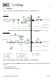
7 FUNCTION Figure 1 shows the function diagram of M&C combustion air conditioning units. Version BA Connection for oilfree compressed air resp.
The inlet pressure is maximum 5.8bar and is limited by relief valve YD2 (works setting). The catalyst F13 is arranged downstream of a pressure regulator YD1. Via a control knob on the front panel of the combustion air conditioning unit, the outlet pressure can be regulated up to maximum 4bar by the customer. Pressure gauges P1 and P2 on the front panel of the BA... enable visualisation and monitoring of the inlet and outlet pressure.
Catalytic oxidation Fl3 of the hydrocarbons at a temperature of 500°C on the surface of the platinum/palladium filling. The optimal catalyst temperature is preset at the works at temperature controller B1 on the front panel of the combustion air conditioning unit. In the event of deviation of the temperature within a temperature range of 10°C, the gas flow is automatically interrupted and the solenoid valve Y1 for pressure relief in the combustion air conditioning unit is opened.
9 DESCRIPTION Figure 2 shows the BA-P4 combustion air conditioning unit.
The catalyst cartridge is installed in a heat-insulated tube furnace. A special screw-type adapter enables removal of the hot catalyst cartridge without the aid of tools (see 15.4). WARNING! EXCESS- PRESSURE The combustion air unit is operated with maximum 5.8bar. Before removing the catalyst cartridge, the system must be relieved of pressure by moving the “Air/ON” switch into the lower position! In the event of incorrect operation, i.e.
10 RECEIPT AND STORAGE The BA... combustion air conditioning unit is a complete, pre-installed unit. The standard catalyst and adsorber cartridge supplied is already fitted. Immediately remove the combustion air conditioning unit and any special accessories carefully from the packaging and check the contents against the delivery note. Inspect the unit for possible transport damage and inform the transport insurer concerned immediately if any damage is noticed.
12 SUPPLY CONNECTIONS 12.1 HOSE CONNECTIONS Connection to the combustion and waste air outlet takes place at the rear of the combustion air conditioning unit. Provided for this purpose are standard DN 4/6 hose couplers. Do not confuse the hose connections for the combustion and waste air outlet; the connections are marked appropriately. NOTE! When all lines have been connected, they must be checked for leaks (see 15.7).
12.2 ELECTRICAL CONNECTIONS Incorrect system voltage can damage the unit.
For signalling the group alarm, the contacts 5 and 9 are available in the Sub-D-Plug (see Figure 3). This is a floating NO contact with a switching capacity of maximum 24V, 1A. Alarm takes place within a temperature range of 10°C for the nominal temperature and if the inlet pressure falls below a value of 4bar. Control of the “Power/On” and “Air/On” functions (switches on front panel, see Figure 2) can takes place either internally or externally by the customer (see Figure 3).
14 SWITCH OFF NOTE! The place of installation of the combustion air conditioning unit must be remain free from frost also during time when the unit is switched off ! No particular measures are required for switch off. 15 MAINTENANCE Before carrying out maintenance work, the system and process-specific safety measures must be observed! WARNING! High voltage. Disconnect the mains plug before opening the converter housing! The following components of the BA...
15.1 SWING PISTON COMPRESSOR The swing piston compressor does not need to be removed for maintenance purposes. It is recommended to follow the following step by step procedure: Disconnect the mains plug of the combustion air conditioning unit. Disconnect the connecting hoses to the pump. Loosen the four screws in the front panel of the BA and remove the 19” plug-in unit. Loosen the cover of the BA housing by carefully levering and removing upwards.
15.4 CATALYST CARTRIDGE REPLACEMENT Cartridge replacement can take place without the aid of tools. The following steps must be carried out: WARNING! Hot catalyst cartridges. Contact can result in serious burns. Wear protective gloves and secure cartridge against unauthorised access ! Relieve the pressure in the combustion air conditioning unit; switch off the “Air/On” switch internally or externally (LED goes out).
15.5 ADSORBER CARTRIDGE REPLACEMENT The following steps must be carried out: Relieve the pressure in the combustion air conditioning unit; switch off the “Air/On” switch internally or externally (LED goes out). Remove the screw cap by turning counter-clockwise. Remove the adsorber cartridge from the holder by turning the stirrup bolt. Refitting takes place in reverse order. NOTE! 15.
The inner seals can be removed with a pointed tool (e.g. marking tool). When refitting, the outer seals must be slipped over the cartridge into the respective seal groove. The inner seals must be fitted as follows: Place the seal in the adapter opening. Push the O-ring with a blunt object on to the respective seal groove.
16 USE OF THE TEMPERATURE CONTROLLER 16.1 DISPLAY AND FUNCTION KEYS Process value display, red Set-point display, green PGM key - to select the parameters Decrement key - to alter values Increment key - to alter values EXIT key - to quit the levels LED for ramp/programme function, green LED for status indication, yellow - outputs 1 to 3 16.2 499.5 500.
16.3 CHANGING THE PARAMETERS OF THE TEMPERATURE REGULATOR The programming of the regulator is made on different levels. All important adjustments of the converter are listed in the user level and can be modified after removing the key locking. In order to remove the locking, please proceed as follows: Standard indication (setting value below, actual value above (see photo)) must to be seen.
16.4 RESET OF THE CONTROLLER A reset out of the temperature lock happens with connected mains: operating simultaneously the keys EXIT and A reset only happens in case the actual temperature deviates by < +/- 10°C from the theoretical temperature. Another method for a reset that functions without problem is to cut the mains voltage for a short moment (remove the mains plug). NOTE! Watch carefully the control characteristic after reset.
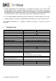
17 TROUBLE SHOOTING The table below is intended to indicate possible causes of faults and the remedial actions to be taken (applies only to operationally ready combustion air conditioning units). Problem/Indication LED‟s do not light, pump does not pump or three-way directional control valves do not switch, temperature controller does not function. Tube furnace does not heat. Pump does not pump or three-way directional control valve does not switch, LED‟s do not light.
18 SPARE PART LIST Wear, tear and replacement part requirements depend on specific operating conditions. The recommended quantities are based on experience and are not binding. Combustion Air Conditioning BA ... (C) Consumable parts, (R) recommended spare parts, (S) spare parts recommended quantity for BA... being in operation [years] (b.d. = by demand) 96 A 0010 V/E/T 1 2 3 C b.d. b.d. b.d. C b.d. b.d. b.d.
Figure 5 Circuit diagram BA... with controller 703/70304 Gas sampling and conditioning technology 10-1.
Figure 6 Circuit diagram BA... with controller TM48 Gas sampling and conditioning technology 10-1.