Instruction Manual Air Conditioning Unit Series BA Version BA-C Gas sampling and gas conditioning technology 10-1.1.
Content 1 General information ............................................................................................................... 4 2 Declaration of conformity ...................................................................................................... 4 3 Safety instructions ................................................................................................................. 5 4 Warranty ...................................................................................
Dear customer, we have made up this operating manual in such a way that all necessary information about the product can be found and understood quickly and easily. Should you still have any question, please do not hesitate to contact M&C directly or go through your appointed dealer. Respective contact addresses are to be found in the annexe to this operating manual. Please also contact our homepage www.mc-techgroup.com for further information about our products.
Head Office M&C TechGroup Germany GmbH Rehhecke 79 40885 Ratingen Germany Telephone: 02102 / 935 - 0 Fax: 02102 / 935 - 111 E - mail: info@mc-techgroup.com www.mc-techgroup.com 1 GENERAL INFORMATION The product described in this operating manual has been examined before delivery and left our works in perfect condition related to safety regulations. In order to keep this condition and to guarantee a safe operation, it is important to heed the notes and prescriptions made in this operating manual.
3 SAFETY INSTRUCTIONS Please take care of the following basic safety procedures when mounting, starting up or operating this equipment: Read this operating manual before starting up and use of the equipment. The information and warnings given in this operating manual must be heeded. Any work on electrical equipment is only to be carried out by trained specialists as per the regulations currently in force.
5 USED TERMS AND SIGNAL INDICATIONS DANGER! This means that death, severe physical injuries and/or important material damages will occur in case the respective safety measures are not fulfilled. WARNING! This means that death, severe physical injuries and/or important material damages may occur in case the respective safety measures are not fulfilled. This means that minor physical injuries may occur in case the respective safety measures are not fulfilled.
6 INTRODUCTION The M&C BA-C air conditioning unit has been designed especially for applications where dry, cleaned and hydrocarbon-free air is required, independent of gas cylinders. Typical applications are hydrocarbon measurements with flame ionisation detectors (FID) and use as a zero gas generator for the calibration of infrared (IR) analyzers or for production of dilution gas for M&C dilution probes.
Gas conditioning section: The second cleaning stage are two mol sieve columns removing CO2 and moisture (Fl2 and FI3) being switched and purged resp. regenerated cyclical. The inlet pressure is 70 - 145 psig. The manometer P1 on the front plate of the BA-C enables the optical control of the inlet pressure. The cleaned air is available at the outlet 2. Here a connector G ¼“ i provided by customer can be mounted.
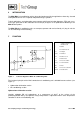
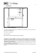
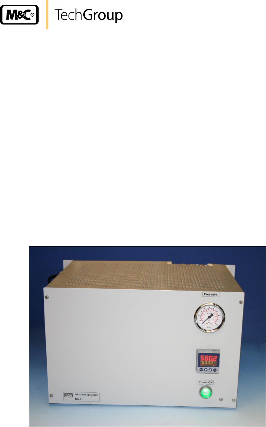
9 DESCRIPTION P1 B1 S1 Figure 2 BA-C air conditioning unit All controls and indicating elements are arranged easily accessible on the front panel of the combustion air conditioning unit: P1: Inlet pressure gauge P1 S1: Main switch S1 B1: Temperature controller with digital temperature display B1 The M&C air conditioning unit BA-C is a compact, easy to handle and maintain wall mounting device. By rebuilding the mounting brackets the air conditioning unit is also applicable for 19“-rack mounting.
10 RECEIPT AND STORAGE The BA-C combustion air conditioning unit is a complete, pre-installed unit. The standard catalyst and adsorber cartridge supplied is already fitted. The filter to be connected upstream is attatched to the device. Immediately remove the air conditioning unit and any special accessories carefully from the packaging and check the contents against the delivery note.
REBUILDING FOR 19“-RACK-MOUNTING 11.1 The deliverd device is prepared for wall mounting. For 19“-rack-mounting the two mounting brackets have to be disconnected from the back side and fixed to the front side. For one side as a start act as follows: Unscrew the three screws at the front of the sidewall. Unsrew the two upper screws at the mounting bracket and only loosen the third to turn the bracket to the back. Screw in now the two screws again.
12.2 HOSE CONNECTIONS The connection of the air in- and outlet take place on the top for wall mounting and at the back side for 19“-rack-mounting. 19“-Mounting Figure 4 Wall mounting Hose connections for wall mounting or 19“-rack-mounting For rebuilding the connections (G1/4“i) on the top or back side the blind plugs have to be displaced correspondingly. HINWEIS! Do not exchange the tube connections for inlet and outlet; the connections are marked correspondingly.
13 INITIAL OPERATION Prior to initial operation, the system and process-specific safety measures must be observed ! The following steps must be carried out prior to initial operation: Prior to initial operation, compare the system voltage with the voltage shown on the rating plate; Connect the air conditioning unit to the mains; Connect status contact ouput, if necessary ; Operate the “Power/On” switch (green LED lights).
WARNING! 15.1 Also after switching off the mains voltage touching the catalyst cartridge can lead to serious burns. Wear protective gloves. THE EXTERNAL PARTICLE-CONDENSATE-FILTER WARNING! The air conditioning is operated with max. 145 psi inlet pressure. Before maintaining the filter the device has to be disconnected from the pressure air.
16 APPENDIX Circuit diagram BA-C More product documentation is available on our Internet catalogue: www.mc-techgroup.com Gas sampling and gas conditioning technology 10-1.1.
Figure 5 Circuit diagram BA-C Gas sampling and gas conditioning technology 10-1.1.