
Installation guide


TimewARP 2600 Getting Started Guide
13
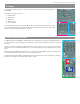
Ring Modulator
The Ring Modulator ❶ adds or subtracts the inputs from VCO1 and VCO2 together. It works with a carrier signal and
a modulator. The term “Ring Modulator” is the most common name in sound synthesis and comes from the original
analog method for creating this effect: a ring with four paired diodes accompanied by precision transformers.
When you add and subtract two signals in the Ring Modulator, the outcome signals are called sidebands. The most
known sounds produced by the Ring Modulator are bell/metallic sounds, or the “robotic voice” vocoder effect. The
Ring Modulator module not only affects the pitch and timbre of sounds, it can also be used for all kinds of amplitude
effects like echoes, gating, tremolos, etc.
The kind of transformation this effects on input signals depends to a large extent on what they are and on whether the
modulator is AC or DC coupled to them. This is selected by the Audio/DC switch ❷ at the bottom of the modulator.
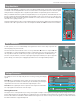
Noise Generator
In audio synthesis, noise is an extraordinarily useful signal. Filters can be used to shape a spectrum into
almost anything–even pitched sounds.
The Noise Generator has two manual controls: one for spectral balance
❶ and one for output level ❷. The
spectral balance is continuously variable from white to red (low-frequency noise output). In the latter case,
the output falls off at the rate of 6dB/octave; the pink noise position approximates a -3dB/Octave slope.
The level control, at minimum, cuts off the output signal completely. At maximum, the output is clipped to
produce binary, or two-valued, noise. Clipping begins with the level control approximately half open.
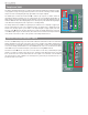
Voltage Processors
The Voltage Processors are simple utility functions for mixing, inverting, and shaping
signals.
VP #1
❶ has four signal inputs and one output. Two of the inputs have attenuators.
The output signal is the inverted sum of all four inputs. The attenuator-governed inputs
carry default connections from +10V and from the keyboard pitch-control.
VP #2
❷ has two signal inputs and one output. One of the inputs has an attenuator.
The output signal is the inverted sum of the two inputs.
The Lag Processor ❸
The Lag Processor is a low-pass filter for processing control signals. It reshapes control signals by slowing down abrupt changes and is used to
produce glides and swoops. The slider adjusts its cutoff frequency. The corresponding rise-time ranges from 0.5ms with the slider at minimum, to
500msec–about half a second–with the slider at maximum. The Lag Processor can be used to process audio signals, as a -6dB/octave manual
filter with a maximum Fc of approximately 1kHz.