
User Guide for FSR Sensor


FSR Integration Guide and Evaluation Parts Catalog Page 9
with Suggested Electrical Interfaces
• Keep actuation cycle time consistent. Because of the time dependence of the FSR resistance to an
applied force, it is important when characterizing the sensor system to assure that increasing loads
(e.g. force ramps) are applied at consistent rates (cycle-to-cycle). Likewise, static force
measurements must take into account FSR mechanical setting time. This time is dependent on the
mechanics of actuation and the amount of force applied and is usually on the order of seconds.
4. Use the Optimal Electronic Interface
In most product designs, the critical characteristic is Force vs. Output Voltage, which is controlled by the
choice of interface electronics. A variety of interface solutions are detailed in the TechNote section of
this guide. Summarized here are some suggested circuits for common FSR applications.
• For FSR Pressure or Force Switches, use the simple interfaces detailed on pages 16 and 17.
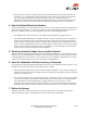
• For dynamic FSR measurements or Variable Controls, a current-to-voltage converter (see pages 18
and 19) is recommended. This circuit produces an output voltage that is inversely proportional to
FSR resistance. Since the FSR resistance is roughly inversely proportional to applied force, the end
result is a direct proportionality between force and voltage; in other words, this circuit gives roughly
linear increases in output voltage for increases in applied force. This linearization of the response
optimizes the resolution and simplifies data interpretation.
5. Develop a Nominal Voltage Curve and Error Spread
When a repeatable and reproducible system has been established, data from a group of FSR parts can be
collected. Test several FSR parts in the system. Record the output voltage at various pre-selected force
points throughout the range of interest. Once a family of curves is obtained, a nominal force vs. output
voltage curve and the total force accuracy of the system can be determined.
6. Use Part Calibration if Greater Accuracy is Required
For applications requiring the highest obtainable force accuracy, part calibration will be necessary. Two
methods can be utilized: gain and offset trimming, and curve fitting.
• Gain and offset trimming can be used as a simple method of calibration. The reference voltage and
feedback resistor of the current-to-voltage converter are adjusted for each FSR to pull their responses
closer to the nominal curve.
• Curve fitting is the most complete calibration method. A parametric curve fit is done for the nominal
curve of a set of FSR devices, and the resultant equation is stored for future use. Fit parameters are
then established for each individual FSR (or sending element in an array) in the set. These
parameters, along with the measured sensor resistance (or voltage), are inserted into the equation to
obtain the force reading. If needed, temperature compensation can also be included in the equation.
7. Refine the System
Spurious results can normally be traced to sensor error or system error. If you have any questions,
contact Interlink Electronics’ Sales Engineers to discuss your system and final data.