
User Guide for FSR Sensor

Page 24 FSR Integration Guide and Evaluation Parts Catalog
with Suggested Electrical Interfaces
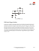
Additional FSR Current-to-Voltage
Converters
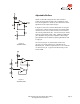
These circuits are a slightly modified version of the
current-to-voltage converter detailed on the previous
page. Please refer to it for more detail.
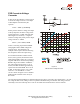
The output of Figure 16 is described by the equation:
VOUT = [VREF/2] * [1-RG/RFSR]
The output swing of this circuit is from (VREF/2) to
0V. In the case where RG is greater than RFSR, the
output will go into negative saturation.
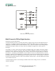
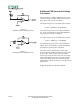
The output of Figure 17 is described by the equation:
VOUT = VREF/2 • [1 + RG/RFSR].
The output swing of this circuit is from (VREF/2) to
VREF. In the case where RG is greater than RFSR,
the output will go into positive saturation.
For either of these configurations, a zener diode
placed in parallel with RG will limit the voltage built
up across RG. These designs yield one-half the
output swing of the previous circuit, but only require
single sided supplies and positive reference voltages.
Like the preceding circuit, the current through the
FSR should be limited to less than 1 mA/square cm of
applied force.
Suggested op-amps are LM358 and LM324.
Figure 16
Add’l FSR Current-to-Voltage Converter
Figure 17
Add’l FSR Current-to-Voltage Converter