
User Guide for FSR Sensor


FSR Integration Guide and Evaluation Parts Catalog Page 23
with Suggested Electrical Interfaces
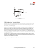
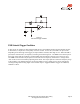
FSR Current-to-Voltage
Converter
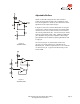
In this circuit, the FSR device is the input of
a current-to-voltage converter. The output
of this amplifier is described by the
equation:
VOUT = VREF • [-RG/RFSR].
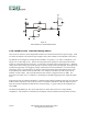
With a positive reference voltage, the output
of the op-amp must be able to swing below
ground, from 0V to –VREF, therefore dual
sided supplies are necessary. A negative
reference voltage will yield a positive output
swing, from 0V to +VREF.
VOUT = (-RG • VREF) /RFSR.
VOUT is inversely proportional to RFSR.
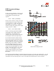
Changing RG and/or VREF changes the
response slope. The following is an
example of the sequence used for choosing
the component values and output swing:
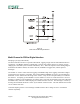
For a human-to-machine variable control
device, like a joystick, the maximum force
applied to the FSR is about 1kg. Testing of
a typical FSR shows that the corresponding
RFSR at 1kg is about 4.6kΩ. If VREF is –
5V, and an output swing of 0V to +5V is
desired, then RG should be approximately
equal to this minimum RFSR. RG is set at
4.7kΩ. A full swing of 0V to +5V is thus
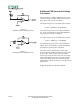
achieved. A set of FORCE vs. VOUT
curves is shown in Figure 15 for a standard
FSR using this interface with a variety of
RG values.
The current through the FSR device should be limited to less than 1 mA/square cm of applied force. As with
the voltage divider circuit, adding a resistor in parallel with RFSR will give a definite rest voltage, which is
essentially a zero-force intercept value. This can be useful when resolution at low forces is desired.
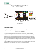
Figure 15
FSR Current-to-Voltage Converter