
User Guide for FSR Sensor


Page 22 FSR Integration Guide and Evaluation Parts Catalog
with Suggested Electrical Interfaces
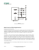
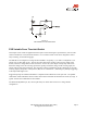
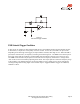
FSR Variable Force Threshold Relay Switch
This circuit is a derivative of the simple FSR Variable Force Threshold Switch on the previous page. It has
use where the element to be switched requires higher current, like automotive and industrial control relays.
The FSR device is arranged in a voltage divider with RM. An op-amp, U1, is used as a comparator. The
output of U1 is either high or low. The non-inverting input of the op-amp sees the output of the divider,
which is a voltage that increases with force. At zero force, the output of the op-amp will be low. When the
voltage at the non-inverting input of the op-amp exceeds the voltage of the inverting input, the output of the
op-amp will toggle high. The triggering voltage, and therefore the force threshold, is set at the inverting
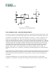
input by the pot R1. The transistor Q1 is chosen to match the required current specification for the relay.
Any medium power NPN transistor should suffice. For example, an NTE272 can sink 2 amps, and an
NTE291 can sink 4 amps. The resistor R3 limits the base current (a suggested value is 4.7kΩ). The
hysteresis resistor, R2, acts as a “debouncer’, eliminating any multiple triggerings of the output that might
occur.
Suggested op-amps are LM358 and LM324. Comparators like LM393 and LM339 also work quite well, but
must be used in conjunction with a pull-up resistor. The parallel combination of R2 with RM is chosen to
limit current and to maximize the desired force sensitivity range. A typical value for this combination is
about 47kΩ.
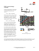
The threshold adjustment pot, R1, can be replaced by two fixed value resistors in a voltage divider
configuration. The diode D1 is included to prevent flyback, which could harm the relay and the circuitry.
Figure 14
FSR Variable Force Threshold Relay Switch