
User Guide for FSR Sensor


FSR Integration Guide and Evaluation Parts Catalog Page 21
with Suggested Electrical Interfaces
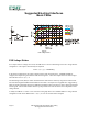
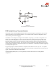
FSR Variable Force Threshold Switch
This simple circuit is ideal for applications that require on-off switching at a specified force, such as touch-
sensitive membrane, cut-off, and limit switches. For a variation of this circuit that is designed to control
relay switching, see the following page.
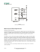
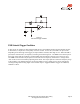
The FSR device is arranged in a voltage divider with RM. An op-amp, U1, is used as a comparator. The
output of U1 is either high or low. The non-inverting input of the op-amp is driven by the output of the
divider, which is a voltage that increases with force. At zero force, the output of the op-amp will be low.
When the voltage at the non-inverting input of the op-amp exceeds the voltage of the inverting input, the
output of the op-amp will toggle high. The triggering voltage, and therefore the force threshold, is set at the
inverting input by the pot R1. The hysteresis, R2, acts as a “debouncer”, eliminating any multiple triggerings
of the output that might occur.
Suggested op-amps are LM358 and LM324. Comparators like LM393 also work quite well. The parallel
combination of R2 with RM is chosen to limit current and to maximize the desired force sensitivity range. A
typical value for this combination is about 47kΩ.
The threshold adjustment pot, R1, can be replaced by two fixed value resistors in a voltage divider
configuration.
Figure 13
FSR Variable Force Threshold Switch