
User Guide for FSR Sensor

Page 20 FSR Integration Guide and Evaluation Parts Catalog
with Suggested Electrical Interfaces
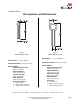
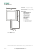
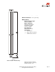
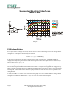
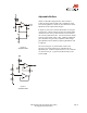
Multi-Channel to FSR-to-Digital Interface
Sampling Cycle (any FSR channel):
The microcontroller switches to a specific FSR channel, toggling it high, while all other FSR channels are
toggled low. The RESET channel is toggled high, a counter starts and the capacitor C1 charges, with its
charging rate controlled by the resistance of the FSR (t ~ RC). When the capacitor reaches the high digital
threshold of the INPUT channel, the counter shuts off, the RESET is toggled low, and the capacitor
discharges.
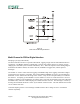
The number of “counts” it takes from the toggling of the RESET high to the toggling of the INPUT high is
proportional to the resistance of the FSR. The resistors RMIN and RMAX are used to set a minimum and
maximum “counts” and therefore the range of the “counts”. They are also used periodically to re-calibrate
the reference. A sampling cycle for RMIN is run, the number of “counts” is stored and used as a new zero.
Similarly, a sampling cycle for RMAX is run and the value is stored as the maximum range (after subtracting
the RMIN value). Successive FSR samplings are normalized to the new zero. The full range is “zoned” by
dividing the normalized maximum “counts” by the number of desired zones. This will delineate the window
size or width of each zone.
Continual sampling is done to record changes in FSR resistance due to change sin force. Each FSR is
selected sequentially.
Figure 12
Multi-Channel FSR-to-Digital Interface