
User Guide for FSR Sensor

FSR Integration Guide and Evaluation Parts Catalog Page 19
with Suggested Electrical Interfaces
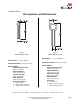
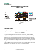
Adjustable Buffers
Similar to the FSR Voltage Divider, these interfaces
isolate the output from the high source impedance of the
Force Sensing Resistor. However, these alternatives allow
adjustment of the output offset and gain.
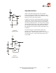
In Figure 10, the ratio of resistors R2 and R1 sets the gain
of the output. Offsets resulting from the non-infinite FSR
resistance at zero force (or bias currents) can be trimmed
out with the potentiometer, R3. For best results, R3 should
be about one-twentieth of R1 or R2. Adding an additional
pot at R2 makes the gain easily adjustable. Broad range
gain adjustment can be made by replacing R2 and R1 with
a single pot.
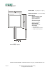
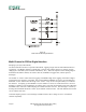
The circuit in Figure 11 yields similar results to the
previous one, but the offset trim is isolated from the
adjustable gain. With this separation, there is no constraint
on values for the pot. Typical cal for R5 and the pot are
around 10kΩ.
Figure 10
Adjustable Buffer
Figure 11
Adjustable Buffer