
User Guide for FSR Sensor

Page 18 FSR Integration Guide and Evaluation Parts Catalog
with Suggested Electrical Interfaces
Suggested Electrical Interfaces
Basic FSRs
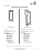
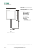
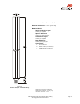
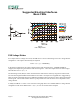
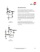
FSR Voltage Divider
For a simple force-to-voltage conversion, the FSR device is tied to a measuring resistor in a voltage divider
configuration. The output is described by the equation:
VOUT = (V+) / [1 + RFSR/RM].
In the shown configuration, the output voltage increases with increasing force. If RFSR and RM are
swapped, the output swing will decrease with increasing force. These two output forms are mirror images
about the line VOUT = (V+) / 2.
The measuring resistor, RM, is chosen to maximize the desired force sensitivity range and to limit current.
The current through the FSR should be limited to less than 1 mA/square cm of applied force. Suggested op-
amps for single sided supply designs are LM358 and LM324. FET input devices such as LF355 and TL082
are also good. The low bias currents of these op-amps reduce the error due to the source impedance of the
voltage divider.
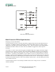
A family of FORCE vs. VOUT curves is shown on the graph above for a standard FSR in a voltage divider
configuration with various RM resistors. A (V+) of +5V was used for these examples.
Figure 9
FSR Voltage Divider