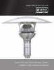
MAKE THE MOST OF YOUR LYNX POST MOUNTED HEATER (LHPM) CARE & USE/INSTALLATION
WARNINGS WARNING READ THIS MANUAL CAREFULLY and completely before using your grill to reduce the risk of: 1. Fire 2. Burn hazard, personal injury or property damage 3. Unapproved installation or servicing. THIS PRODUCT IS DESIGNED FOR OUTDOOR RESIDENTAL USE ONLY. Improper installation, adjustment, alteration, service or maintenance can cause injury or property damage. Read the installation, operating and maintenance instructions thoroughly before installing or servicing this equipment.
IMPORTANT The installer must leave these instructions with the owner. Only those who are certified to do so should perform service on these heaters. CAUTION AND GENERAL SAFETY • At all times maintain clearance to combustible materials as further specified in this manual. Failure to do so can result in serious fire hazazrd. • Never operate heaters in atmosphere containing flamable vapours or combustible dusts. • This heater is equipped with an electronic and automatic ignition device.
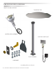
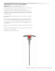
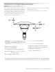
PRE-INSTALLATION OVERVIEW WHAT YOU WILL RECEIVE: TOP REFLECTOR HEATER HEAD ASSEMBLY ELECTRIC SWITCH KIT POLE ASSEMBLY HARDWARE Assembly delivers in 4 boxes 4 | LHPM POST MOUNTED HEATER CARE & USE/INSTALLATION
A MESSAGE TO OUR CUSTOMERS Lynx manufactures many accessory cooking appliances to compliment your Lynx grill and your desire for truly superior cooking results. Your appliance has been designed and built with meticulous attention to detail and it offers some unique and powerful features. You can achieve maximum performance and enjoyment of these features only by carefully reading this manual. This manual includes important safety tips. You should keep it handy for easy reference.
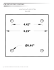
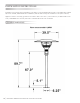
PRE-INSTALLATION OVERVIEW MOUNTING PLATE HOLE PATTERN (FULL SIZE) 6 | LHPM POST MOUNTED HEATER CARE & USE/INSTALLATION
LIGHTING INSTRUCTIONS WARNING Read the ‘User Manual/Installation Instructions carefully and completely before using your heater to reduce the risk of fire, burn hazard or other injury. LIGHTING 1. Open manual gas supply valve (ensure gas supply lines have been purged). 2. Turn on switch to energize electric supply. 3. The electronic control module will begin the ignition period in 3 seconds. 4. The gas valve will open and ignition spark will commence and continue for 20 sec. 5.
LOCATION PLANNING Wind protection has an important influence on the human body’s ability to retain radiant heat. Use natural or newly built wind barriers where possible, such as existing buildings, shrubbery or tree lines and fences. One Lynx Patio heater, at high fire and in windless conditions has a comfort radius of about twelve feet. A series of heaters providing area heat should be placed about 14 feet apart. WARNING This heater is NOT approved for any indoor Residential application.
CLEARANCE TO COMBUSTIBLE MATERIALS The following clearance data is based on a maximum limit of 90°F plus ambient temperature. Note with an ambient temperature of 70°F the surface temperatures at the clearance distances listed below could reach 160°F. Care should be taken with placement of plastic or vinyl in the proximity of the heater as they tend to distort and soften at these temperatures. 18” NOTE: Some materials deteriorate or soften at sustained temperatures below 160°F.
INSTALLATION INSTRUCTIONS Installation must comply with local building codes and/or, for the USA/National Fuel Gas Code, ANZI Z 223.1 (NFPA 54) and for Canada, CAN/CGA B149.1 and B149.2, National Gas and Propane Installation Code (latest editions). Appliance must be electrically grounded in accordance with local codes or, in their absence; the National Electrical Code, ANSI/NFPA 70 in the USA, CSA CZ21.1 Canadian Electrical Code in Canada.
ASSEMBLY Mount pole base onto a concrete floor or cast concrete with minimum below grade depth of 12” and having a 12” diameter. If forming concrete, cast in place appropriate passage for gas and control wires. Use minimum 3/8” x 5” 90° lag bolts or equivalent to mount heater base to the concrete base. The pole base could also be mounted on wood decks with 3/8” bolts and lock washers on the underside of the deck. Periodically check for tightness when mounted to a wood deck.
ASSEMBLY...continued Arrange the burner head such that the wires and gas hose are arranged as illustrated. Feed a pull wire through the pole to assist in pulling the three power wires into the pole and through the junction box. Firmly tape the pull wire to the power wires. Lower the assembly into place while pulling the wires. Two people may be necessary for this operation.
ASSEMBLY...
ASSEMBLY...continued Push the gas connection into the slot buy slightly pushing on the gas line through the electrical box. The gas fitting should be positioned as illustrated below.
ASSEMBLY...continued Place gas connection cover onto the fitting and install the nut to fasten the cover assuring the nut is properly seated. See below.
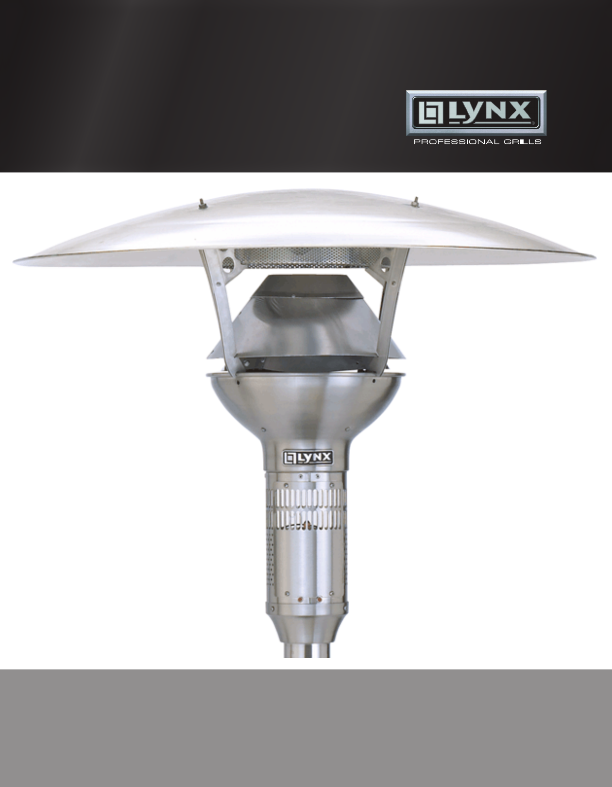
ASSEMBLY...continued Install reflector using the four carriage bolts, nuts and washer provided. STEP 6 Connect gas supply and electric power following all local codes. Pressure test all gas connections.
ASSEMBLY...continued The switch assembly contains three colored leads that match the corresponding colors from the heater. Connect the matching wire colors to each other with an appropriate length of wire. We recommend a minimum 18 AWG gauge wire rated for outdoor use. STEP 7 This wiring kit is provided with a 24 Volt AC supply with a minimum 20 VA capacity. The wiring kit provides one black lead for connection of the switch to the transformer.
SCHEMATICS TThis appliance requires a 24 volt AC supply with a minimum 20 VA capacity. Below is a suggested control circuit for operating this appliance. The switching mechanisms may also be Timers. MAINTENANCE AND TROUBLESHOOTING MAINTENANCE • Before performing any service shut off gas and electric supply. • Check condition of burner, especially integrity of flame screen. • Inspect condition of spark and sense electrode. Check for cracks in ceramic insulators or excessive corrosion.
PARTS LIST ITEM A B DESCRIPTION REFLECTOR PACKAGE GAS HOSE ASSEMBLY PART # 32591 33285 ITEM G H DESCRIPTION ORIFICE NAT GAS GAS VALVE ASSEMBLY PART # 33290 33291 C D EMITTER FLAME SENSOR 33286 33287 E F SPARK ELECTRODE 33288 ELECTRONIC CONTROL MODULE 33289 I J K L INDICATOR LIGHT BURNER ASSEMBLY POLE PACKAGE IGNITION WIRE 33292 33293 32590 33294 LHPM POST MOUNTED HEATER CARE & USE/INSTALLATION | 19
INTERNAL WIRING 20 | LHPM POST MOUNTED HEATER CARE & USE/INSTALLATION
LYNX LHPM LIMITED WARRANTY I. LIMITED FIVE-YEAR WARRANTY homes, food service locations and institutional food service locations. Lynx warrants to the original owner that the product will be free of defects in material and workmanship for a period of 5 years from the date of purchase. This warranty is limited to the replacement of the defective parts, with the owner paying all other costs including labor, shipping, and handling.
The best outdoor kitchen products come from: Lynx Grills, Inc. 7300 Flores Street Downey, CA 90242 Service: (888)-289-5969 Fax: (562) 299-6789 www.lynxgrills.