Model No. LHFS Infrared Outdoor Patio Heater Manual for Installation, Operation & Maintenance DANGER If you smell gas: 1. Shut off gas to appliance. 2. Extinguish any open flame. 3. If odor continues, keep away from the appliance and immediately call your gas supplier or fire department. WARNING: Do not store or use gasoline or other flammable vapors and liquids in the vicinity of this or any other appliance.
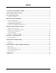
INDEX CAUTION AND GENERAL SAFETY ......................................................................................... 3 APPLICABLE REGULATIONS ................................................................................................... 5 LOCATION PLANNING ............................................................................................................... 6 SAFETY REQUIREMENTS ..............................................................................................................
Caution and General Safety CAUTION: FIRE OR BURN INJURY HAZARD WARNING: Do not install or place on a table or on an inclined surface, make sure the installation surface is level before installing the heater. • Assembly & Installation will require the efforts of Two individuals, it is not recommended for only One Person to attempt complete assembly of the Heater. • At all times maintain clearance to combustible materials as further specified in this manual.
Caution and General Safety • NEVER paint the Burner, Emitter, Shield Support Arms or the Reflector. • The visible portion of the Hose Assembly must be visually inspected before each use. If there is evidence of excessive abrasion or wear, or if the hose is damaged the hose assembly must be replaced prior to the appliance being put into operation. • This appliance shall be used only in a well-ventilated area/space and shell not be used in a building, garages or any other enclosed area.
Applicable Regulations • Installation must comply with local building codes or, in their absence, the latest edition of the applicable national codes: USA - National Fuel Gas Code, ANSI Z 223.1 (NFPA 54), Canada - National Gas and Propane Installation Code, CAN/CGA B149.1.
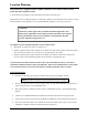
Location Planning One Patio heater, at high fire and in windless conditions, has a comfort radius of about twelve feet (24 ft. diameter circle). A series of heaters providing area heat should be placed about 14-20 feet apart. Wind protection has an important influence on the body’s ability to retain radiant heat. Use natural or newly built wind barriers where possible, such as existing buildings, shrubbery or tree lines and fences WARNING! This heater is NOT approved for any indoor Residential application.
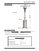
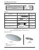
Specifications / Details Equipment Dimensions Model # LHFS LP-Gas Cylinder Compatibility To be used ONLY with 20 lb LP-Gas Cylinders with a maximum capacity of 8kg (20 lb) which meet the criteria described in the Applicable Regulations section of this manual. The Cylinder and its connector fittings must be maintained in good condition. Gas & Power Specifications Maximum Fire Rate: 46,000 BTU/hr Gas Manifold Pressure: 11” W.C.
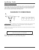
Specifications / Details Clearance to Combustible Materials The following clearance data is based on a maximum limit of 90°F (32 °C) plus ambient temperature. Note with an ambient temperature of 70°F the surface temperatures at the clearance distances listed below could reach 160°F. Care should be taken with placement of plastic or vinyl in the proximity of the heater as they tend to distort and soften at these temperatures. CLEARANCE TO COMBUSTIBLES TOP SIDE MODEL No.
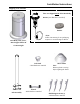
Installation Instructions Shipping Crate Contents These are shipped Inside of the Base Body Burner (with Hardware attached) Emitter *Note: Follow instructions for un-packaging sequence to avoid damage to Burner Base Body, Base Cover, Base Support Pillars & Counterweight Pole Neck - With Hardware attached Pole Assembly Lynx Model No.
Installation Instructions Additional Parts: Base Bracket (3) - with Hardware attached “AA” Battery (1) Hardware: Description Drawing / Picture Used On M8-1.25 X 90 mm Hex Head Carriage Bolt (6) - S/S To hold pole to base support 1/4” - 20 x 1/2" Truss Head Screw with Nut (4) To hold reflector ∅8M-1.25 X 65 mm Anchor Bolt (3) To hold down heater to concrete foundation. #10 x 1 1/2” Wood Screw (3) To hold down heater to wooden deck.
Installation Instructions Assembly of Outdoor Patio Heater 1. Disassemble shipped parts: a. Remove the Base Cover from the Base Body by unscrewing the eight (8) screws holding the Base Cover on. b. Open the Door of the Base Body by pushing down on the handle to disengage the door from the latch. Carefully cut the zip ties holding the Gas Hose Assembly to the interior of the Base Body and remove the Burner.
Installation Instructions 3. Connect a Base Bracket, using the hardware attached to it (1/4-20 x 1/2 Truss Head Bolts), at each set of two (2) holes located around the Base of the Heater (total of three Base Brackets). Assemble so that the heads of the Screws are seen from the outside of the Base. The side of the Bracket with the remaining hole should be flat against the Floor / Ground. Screws Base Bracket Base Bracket 4. Assemble the Pole and the Base Support Pillars together using six (6) M8-1.
Installation Instructions 5. Slide the Base Cover down over the top of the Pole. Reassemble the Base Cover with the Base Body using the eight (8) screws removed previously in Step 1-b. OPTIONAL TABLE Installation Point: Slide the Table down over the top of the Pole, position it in place 8” (200 mm) up from the Base Cover. Secure by tightening the screw(s) of the Table Clamp around the inside neck of the Table and the Pole so that the Table will not move. 200 mm Lynx Model No.
Installation Instructions 6. Remove the three (3) #10-24 x 3/8” screws near the bottom of the Burner and the three (3) screws in the Base of the Pole Neck piece. Insert the Gas Hose Assembly (with regulator attached) through the Pole Neck. Secure the Burner Head to the Pole Neck using the three (3) screws which were removed from the Burner. BURNER 2 1 POLE NECK 7. Assemble the Shield Support Arms to the Burner housing using the Two (2) M4-0.7 x 10mm screws and nut sets shipped on each arm.
Installation Instructions 8. Insert the Outer Shield into the four (4) Shield Support Arms. Make sure to remove (peel off) the plastic covering at before assembly. 9. Remove one of the Fingers from Shield Support Arm then insert the Emitter Ring into the three (3) Shield Support Arms (refer to figure A below), and re-assemble the Finger of last arm (refer to figure B below).
Installation Instructions 10. Insert the Gas Hose Assembly of the Burner (with regulator attached) into the hollow top end of the Pole, and feed it all the way through / down. 11. Secure the Burner Head to the Pole with the Three (3) 1/4”-20 x 1/2" screws previously removed from the Pole Neck piece. Make sure that the Burner Control Panel Knob faces the same direction as the door of Base Body. Lynx Model No. LHFS Page 16 P/N 33348 Rev.
Installation Instructions 12. Install the Top Reflector onto the Shield Support Arms of the Burner using the four (4) 1/4”-20 x 1/2" carriage bolts with nuts provided. Insert the screws up through the Shield Support Arms and then through the Top Reflector. Secure each bolt with a nut on top of the Reflector. Make sure to remove (peel off) the plastic covering before assembly. Warning: This heater is equipped with a tilt / tip switch for your safety.
Installation Instructions Position / Move the Heater 1. Ensure Wheels are properly connected to the Base Body. (Refer to Installation Step 2.) 2. Move the Heater by handling ONLY the Pole or the Base Body. It may take two people to manoeuvre the Heater safely depending on the size / strength of the person(s). 3. Tip the Heater backwards at an angle to / overtop of the wheels until Base no longer touches the ground. Wheel / roll Heater to new location and return Base to ground.
Installation Instructions Secure the Heater 1. Ensure that the Base Brackets are properly installed as described in Installation Step 0. 2. The type of Foundation Fastener required depends on the type of Floor / Ground that the Heater is located upon. Prepare the Floor / Ground as detailed in Table A, at all three bracket locations. (Ensure that alignment with the connecting hole(s) of the Base Bracket is maintained.) Insert / Connect the three Foundation Fasteners as detailed in Table A.
Installation Instructions Connecting the LP-Gas Supply 1. Attach the LP-Gas Cylinder to the Tank Base Retainer using the Cylinder Retention Screw. Make sure the LP-Gas cylinder is in the upright position. Keep gas cylinder Upright Position at ALL times Cylinder retention screw Lynx Model No. LHFS Page 20 P/N 33348 Rev.
Installation Instructions 2. Secure the Gas Hose Regulator onto the LP-Gas Cylinder valve by turning the Regulator clockwise until tight. Before using the patio heater: • Make sure door is shut and stays shut at all time and is not in pedestrian pathway. • Move Heater to desired location. • Secure the Base Body to the floor. • Perform a Leak Test to check the Gas Hose Assembly connections for any gas leaks. Lynx Model No. LHFS Page 21 P/N 33348 Rev.
Testing / Commissioning Leak Test Method Never go over connections looking for leaks with a lighted match, cigarette lighter, or any other flame. Perform the Leak Test before initial lighting and when connecting a new LP-Gas Cylinder. A complete gas tightness check must be performed at the installation on site due to possible miss handing in shipment or excessive pressure being applied to the heater. 1. Make up a dish of soap and water solution of one part liquid detergent and one part water. 2.
Operating Instructions Follow all Caution and General Safety rules at all times before / during use. Lighting 1. Remove the Four (4) screws holding the Valve Housing Cover onto the Burner Housing in order to open the Cover and get access to the Ignitor Module. 2. Unscrew the knob /cover from the Ignitor Module. 3. Take the One (1) AA battery out of the bag / packaging and insert it into the ignitor module, in the orientation as shown in the image below, then put the knob /cover back on.
Maintenance and Trouble Shooting Maintenance ∗ ∗ ∗ Follow Caution and General Safety rules at all times before / during use. Before performing ANY service to the heater, shut off the gas supply, disconnect the regulator from the LP-Gas Cylinder and remove the battery from the ignitor module. If any maintenance issues are found place the heater OUT OF SERVICE until it has been repaired by a certified service person. Use only manufacturer recommended replacement parts. Daily Inspections: 1.
Maintenance and Trouble Shooting Trouble Shooting 1. No gas supply at burner: • Ensure manual shut off valve is in proper position • Ensure there is pressure and flow at inlet to gas valve. • Ensure LP-Gas Cylinder has fuel in it. 2. No spark: • Ensure battery in ignition module is operating. • Ensure spark electrode assembly is grounded and there are no cracks in ceramic insulator. • Ensure the gap (spark gap) between Pilot and Spark Ignitor electrode is 1/8” – 3/16” (3mm – 4.
Maintenance and Trouble Shooting Functional Wiring Diagram Pilot Assembly Ignition Valve Tip Switch Lynx Model No. LHFS Page 26 P/N 33348 Rev.
Maintenance and Trouble Shooting Parts Reference Item Description Part No. Qty Item Description Part No.
Maintenance and Trouble Shooting Lynx Model No. LHFS Page 28 P/N 33348 Rev.
Warranty MODEL No. LHFS - INFRARED OUTDOOR PATIO HEATER WARRANTY The Manufacturer warrants to the original owner that the product will be free of defects in material and workmanship for a period of 5 years from the date of purchase, for everything except the electronic control module, spark electrode, valve, regulator and sense electrodes which have a replacement warranty period of 1 year.