Model No. LHPM Infrared Outdoor Patio Heater Manual for Installation, Operation & Maintenance FOR YOUR SAFETY If you smell gas: 1. Shut off gas to appliance. 2. Extinguish any open flame. 3. If odor continues, immediately call your gas supplier. WARNING: Improper installation, adjustment, alteration, service or maintenance can cause injury or property damage. Read the installation, operating and maintenance instructions thoroughly before installing or servicing this equipment.
INDEX 1) Caution and General Safety ............................................................................ 4 2) Pre-installation Overview ................................................................................ 5 3) What you need to supply ................................................................................. 7 4) Location Planning .............................................................................................8 5) Clearance to Combustible Materials....................
Caution and General Safety CAUTION: FIRE OR BURN INJURY HAZARD Lynx • At all times maintain clearance to combustible materials as further specified in this manual. Failure to do so can result in serious fire hazard. • Never operate heaters in atmosphere containing flammable vapours or combustible dusts. • This heater is equipped with an electronic and automatic ignition device. Do not attempt to light the burner by hand. Failure to comply can result in a serious fire and personal injury hazard.
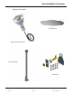
Pre-installation Overview What you will receive: Top Reflector Heater head Assembly Pole Assembly Hardware Lynx Page 5 Rev.
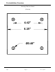
Pre-installation Overview Mounting Plate hole Pattern (Full size) 4.42" 6.25" Ø0.40" Lynx Page 6 Rev.
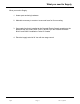
What you need to Supply What you need to Supply: 1. Heater post anchoring hardware. 2. Materials necessary to construct a concrete base for floor mounting. 3. Gas supply line that is installed to the Gas and Electric Supply according to the: National Fuel Gas Code, ANSI Z.223.1 (NFPA 54) in the US and CAN/CGA B149.1 and B149.2 Installation Codes in Canada. 4. Electrical supply rated at 24 Vac with two stage control Lynx Page 7 Rev.
Location Planning Wind protection has an important influence on the body’s ability to retain radiant heat. Use natural or newly built wind barriers where possible, such as existing buildings, shrubbery or tree lines and fences One Lynx Patio heater, at high fire and in windless conditions has a comfort radius of about twelve feet (24 ft. circle). A series of heaters providing area heat should be placed about 14-20 feet apart. WARNING! This heater is NOT approved for any indoor Residential application.
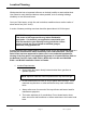
Clearance to Combustible Materials The following clearance data is based on a maximum limit of 90°F plus ambient temperature. Note with an ambient temperature of 70°F the surface temperatures at the clearance distances listed below could reach 160°F Care should be taken with placement of plastic or vinyl in the proximity of the heater as they tend to distort and soften at these temperatures. CLEARANCE TO COMBUSTIBLES TOP SIDE MODEL NO.
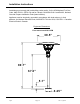
Installation Instructions Installation must comply with local building codes and/or, for the USA/National Fuel Gas Code, ANZI Z 223.1 (NFPA 54) and for Canada, CAN/CGA B149.1 and B149.2, National Gas and Propane Installation Code (latest editions). Appliance must be electrically grounded in accordance with local codes or, in their absence; the National Electrical Code, ANSI/NFPA 70 in the USA, CSA CZ21.1 Canadian Electrical Code in Canada. Equipment Dimensions Floor mount model # LHPM 39.5" 89.7" 67.
Power/Gas Specifications High fire rate: 53,000 btuh Low fire rate: 46,000 btuh Gas supply pressure: Natural Gas: Electric Supply: Minimum Minimum 6.5 ” W.C. Maximum 14” W.C. 24 VAC, 0.8A Installation or repair should only be done by personnel qualified for the installation of powered gas appliances. The appliance and its individual shutoff valve must be disconnected from the gas supply piping system during any pressure testing of that system at test pressures in excess of ½ psig (3.
Assembly a. Mount pole base onto a concrete floor or cast concrete with a minimum below grade depth of 12” and having a 12” diameter. If forming concrete, cast in place appropriate passage for gas and control wires. Use minimum 3/8” x 5” 90° lag bolts or equivalent to mount heater base to the concrete base. The pole base could also be mounted on wood decks with 3/8” bolts and lock washers on the underside of the deck. Periodically check for tightness when mounted to a wood deck. Lynx Page 12 Rev.
Assembly b. Lynx Arrange the burner head such that the wires and gas hose are arranged as illustrated. Feed a pull wire through the pole to assist in pulling the three power wires into the pole and through the junction box. Firmly tape the pull wire to the power wires. Lower the assembly into place while pulling the wires. Two people may be necessary for this operation. Page 13 Rev.
Assembly c. Lynx Secure burner head to pole with three #8 screws provided. Page 14 Rev.
Assembly d. Push the gas connection into the slot buy slightly pushing on the gas line through the electrical box. The gas fitting should be positioned as illustrated below. . Lynx Page 15 Rev.
Assembly e. Place gas connection cover onto the fitting and install the nut to fasten the cover assuring the nut is properly seated. See below. Lynx Page 16 Rev.
Assembly f. Install reflector using the four carriage bolts, nuts and washer provided. g. Connect gas supply and electric power following all local codes. Pressure test all gas connections. Lynx Page 17 Rev.
Wiring This appliance requires a 24 volt AC supply with a minimum 20 VA capacity. Below is a suggested control circuit for operating this appliance. The switching mechanisms may also be Timers Blue Hi Lo To Patio Heater Red On Green Off 24V 20VA Min Lynx 24 120V Ensure a good ground source Page 18 Rev.
Lighting and Shutdown Instructions 1. Lighting a. Open manual gas supply valve (ensure gas supply lines have been purged). b. Turn on switch to energize electric supply. c. The electronic control module will time begin the ignition period in 3 seconds. d. The gas valve will open and ignition spark will commence and continue for 20 sec. e. If flame starts and “is detected”, flame will continue until turned off. f. If no flame is detected, the gas valve will close after 20 sec.
Maintenance and Trouble Shooting Maintenance • • • • • Before performing any service shut off gas and electric supply. Check condition of burner, especially integrity of flame screen. Inspect condition of spark and sense electrode. Check for cracks in ceramic insulators or excessive corrosion. Inspect condition of high tension lead to spark rod. Annually verify hose gas supply in heater post and all connections for gas leaks. Trouble Shooting 1.
Parts List Item A B C D E F Lynx Description Part # Item Reflector package Gas Hose Assembly Emitter Flame Sensor Spark Electrode Electronic Control Module ES041 EG014 ES011 EE002 EE001 EE009 G H I J K M Page 21 Description Part # Orifice Nat Gas Gas Valve Assembly Indicator Light Burner assembly Pole Package Ignition wire EG002 EG007 EE010 EG008 ES066 EE005 Rev.
Internal Wiring Red Red 24 VAC (Lo) Green Green Green Green Pink Green C HI HI LO Yellow Gas Valve Yellow Blue LEDs Spark Electrode If any of the original wire as supplied with the appliance must be replaced, it must be replaced with wiring material having a temperature rating of at least 105°C. Lynx Page 22 Blue 24 VAC (Hi) Si l'un des fils électriques original fournis avec cet appareil doit etre remplacé, le remplace avec un fil électrique fait de la température évaluation d'au moins 105°C.
Warranty MODEL No. LHMP LYNX PATIO HEATER WARRANTY The Manufacturer warrants to the original owner that the product will be free of defects in material and workmanship for a period of 5 years from the date of purchase, for everything except the electronic control module, spark electrode, and sense electrodes which have a replacement warranty period of 3 years. The Manufacturer’s obligation under this warranty is limited to repair or replacement; FOB its facility, of the defective part.