
manual


CARE & USE/INSTALLATION
|
17
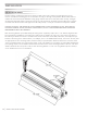
ELECTRICAL CONNECTIONS
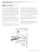
If the AC adaptor is NOT being used, and it is intended to
run the heater from battery power only, then NO
special electrical connections are needed. Note that this
may require more frequent battery replacements. The AC/
DC output plug, at the right end of the heater, is covered
with the rubber plug that is mounted under the jack.
If the AC adaptor IS being used, the battery
function becomes secondary and an approved, GFI
protected, grounded, 110V AC, OUTDOOR outlet box
and electrical receptacle must be installed within 24 in. of
the AC/DC output plug. This outlet must be installed by a
qualified electrician and must be sheltered from rain, snow,
and ice.
Plug the transformer directly into the GFI protected outlet.
Plug the jack, into the corresponding jack receptacle of
the heater. Secure any loose or dangling wires with tape,
wire ties, or insulated wire staples.
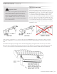
For an alternate to this connection, run an outdoor rated
extension cord from the closest GFI protected 110 V
grounded outlet to the heater. This cord and connection
must be sheltered from the rain and must not be in direct
line with either the heat output of the heater OR the
exhaust gasses exiting the top of the heater. It is
recommended that this cord be secured to the wall ( or
similar structure) with either tape, wire ties or insulated wire
staples. This installation is considered a TEMPORARY
installation.
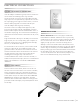
Select a location for this switch, but do not mount it at
this time. Select a location that is out of reach of children,
and is just LOW enough to be reached by an adult. It is
recommended that the wall switch be mounted near the
heater (within 10 ft) so the heater can both be SEEN and
HEARD during operation of the wall switch. This wall
switch mounts on a flat surface with the mounting screws
provided. Double sided tape (not provided) will also work
for this step.
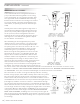
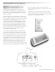
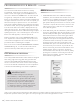
Wireless Wall Switch-This unit uses (2) pre-installed 3V
Lithium Batteries CR2032. If batteries were not previously
installed, remove the cover by inserting a small screw driver
into one of the slots on the side. Twist the screw driver
slightly to snap open the cover from the body. (do not
attampt to remove the small screws at the bottom). Insert
the provided lithium batteries (Posiitive (+) side up), making
sure the edge of the battery is inserted UNDER the small
battery retaining clip. If the wall switch will be mounted with
the provided screws, then mount into position (while the
cover is still off) at this time. After mounted, snap the cover
back onto the wall switch body. See pictures below.
MAKING THE ELECTRICAL CONNECTIONS
WIRELESS WALL SWITCH
BATTERY INSTALLATION