MAKE THE MOST OF YOUR LYNX EAVEMOUNT HEATER (LHEM48) CARE & USE/INSTALLATION
WARNINGS WARNING • Never use dented, rusty or damaged propane cylinders. Never store additional or empty propane cylinders in the vicinity of this or any other appliance. Do not store propane cylinders indoors or on their sides. • Children should never be left alone or unattended in an area where this appliance is located. Install your heater well away from areas where children play. Do not store items that may interest children in or around the area of your heater.
WARNINGS WARNING READ THIS MANUAL CAREFULLY and completely before using your heater to reduce the risk of: 1. Fire 2. Burn hazard, personal injury or property damage 3. Unapproved installation or servicing. THIS PRODUCT IS DESIGNED FOR OUTDOOR USE ONLY. Improper installation, adjustment, alteration, service or maintenance can cause property damage, injury or death. Read this manual thoroughly before installation, use, or servicing of this product.
WARNINGS DANGER - CARBON MONOXIDE HAZARD • This appliance can produce carbon monoxide which has no odor. If not installed, operated, and maintained in accordance with manufacturers instructions, the emissions from this product can cause serious illness or death. Never use this appliance in an enclosed space.
FEATURES Thank you for your purchase of our LYNX Deluxe Eave Mount Patio Heater. This product has been manufactured with the highest quality materials available, and combines the most advanced, state of the art, internal components with cutting edge, heater design technology. This product is sure to provide you many years of enjoyment and comfort.
MOUNTING CONSIDERATIONS Special considerations should be made when selecting a location for your heater before installation. The most important of which should be a location that will serve to be the most functional and useful in providing heat. Suggested locations would be under an eave, on a wall of an open or partially enclosed patio, or on a fascia. This heater has been thoroughly tested and certified to function during and after mild rain storms, and during mild wind conditions.
BEFORE YOU START WARNING SPRINKLERS: This appliance must be located at an appropriate distance away from fire sprinklers (4ft min. recommended) to avoid accidental activation of sprinkler. Ethylene glycol or propylene glycol must never be used in fire sprinkler systems where heaters are present, as these substances may become flammable when heated.
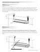
CLEARANCE TO CONSTRUCTION STRAIGHT MOUNTING If the heater is to be mounted facing straight down with no angle on its pivot point, then the heater must be mounted NO CLOSER than 14” from any overhead combustible construction. The side clearances must be NO CLOSER than 12” to a side wall, and the rear clearances must be NO CLOSER than 12” to a rear wall. Use the LOWEST pair of holes in the mounting bracket extension arms. See illustration below.
GAS CONNECTION INFORMATION The heater is factory set to use either propane (LP) or natural gas (NAT). This heater is dedicated to one of these two gas types and it is not easily field convertible. It is critical that the gas you use matches that which the heater was set up for. You can verify that by checking the rating plate. Additionally, each ‘T’ or elbow that is added to the line can also reduce pressure. This drop in pressure can affect overall heater performance.
GAS CONNECTION INFORMATION ...continued A typical gas supply line might consist of ½” piping beginning at the gas supply source. This line will be routed, within the shortest possible distance, up to the vicinity of the heater location (30 Ft. MAX). This line, as previously mentioned, willhave a ½” lever- handled gas shut-off valve installed in-line, and within 6-feet of the termination point.
INSTALLATION MOUNTING THE HEATER Initial mounting considerations have been discussed, and now it’s time commit your placement theory into motion. Consider the following pieces of information to help you through: The Lynx Eave Mount Patio Heater is made from the finest materials available- heavy gauge stainless steel. As a result, this heater is heavy- It weighs around 50 pounds and must be mounted securely.
INSTALLATION...continued EAVE FASCIA MOUNTING Important Note! Use only the mounting brackets provided with this heater. Heater must be installed in a horizontal manner parallel with the ground. The heater can, however, be tilted upward to a maximum of 30 degrees. NEVER mount the heater on a vertical axis. Such an installation is considered unsafe and will void all warranties.
INSTALLATION...continued MOUNTING BRACKET ASSEMBLY Locate and assemble the mounting brackets based on your pre-determined mounting distance to the ceiling (14” if mounting flat, 18” if mounting at an angle). Slide the long bracket extension INSIDE the main mounting bracket until the intended set of holes align. The entrance slot is at the bottom of the main mounting bracket. For each bracket, use quantity (2) ¼-20 x ½” Hex Bolts (provided).
GAS CONNECTIONS MAKING THE GAS CONNECTONS Gas connections will vary depending on heater mounting location selected and the gas type (NG or LP) being used. See also previous section ‘Gas Supply and Connections’. Prior to mounting the heater, the gas connections were considered and an overall routing ‘plan’ was established. A minimum pipe size of ½” is required for inlet piping. The supplied exit coupling of this heater is ½”FIP (female).
GAS CONNECTIONS...continued and re-assemble the pipes and fittings. If a flexible gas line is being used to connect the heater to the hard piping, and the leak is at that section, then be certain the fitting attached to the heater is the proper ½” MIP fitting, and the fitting at the other end is also a ½” MIP fitting used with a ½” coupling to join to the ½” pipe. Very often, a flex hose such as this is created with removable fittings at the ends to create the ½” MIP thread.
ELECTRICAL CONNECTIONS MAKING THE ELECTRICAL CONNECTIONS If the AC adaptor is NOT being used, and it is intended to run the heater from battery power only, then NO special electrical connections are needed. Note that this may require more frequent battery replacements. The AC/ DC output plug, at the right end of the heater, is covered with the rubber plug that is mounted under the jack.
ELECTRICAL CONNECTIONS...continued Touch Screen Remote Transmitter-remove the cover on the back of the remote control unit and install (4) AAA 1.5 V batteries. Take special note of the (+) and (-) terminals. Heater- remove the (2) screws holding the louvered end plate at the far, right end of the heater. This is the SMALLER of the 2 access plates. The battery pack will be mounted directly inside, on the endplate. Using a small Philips head screwdriver remove the screw and slide off the battery box cover.
PROGRAMMING YOUR REMOTE INITIALIZING THE REMOTE CONTROL SYSTEM On the wireless wall switch press the “OFF” button. Confirm that the red LED flashes. The LED will flash every time that any of the 4 buttons are pushed. This confirms that the unit is functioning, and that the button selection has been confirmed. Press the ‘ON’ button on the wall switch to confirm. You will hear ‘clicking’ coming from the heater.
PROGRAMMING YOUR REMOTE...continued Once the wireless wall switch has been successfully programmed, repeat the process with the touch screen remote control. Once again, press the LEARN button on the receiver. Release the LEARN button. You will now hear a single beep. Now push the lower center MODE SET button on the transmitter until the word ‘ON’ is displayed in the upper left hand corner. Once the code is accepted, you will hear four beeps in rapid succession.
PROGRAMMING YOUR REMOTE...continued When the heater is operated for the first time, there may be a certain level of smoke exiting the heater exhaust vents. This may last for up to 15 minutes. This is NORMAL. This is a result of the manufacturing oils, cleaning oils, and antiseize lubricants, burning away under high temperature for the first time. After this ‘break-in’ period, your heater should function normally, emitting no additional smoke.
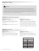
TOUCH SCREEN REMOTE CONTROL MODE Zone AIR TEMP Zone SET TEM P Zone TIME/PROG Zone (Unused) LIGHT Zone (Unused) FLAME Zone AUX Zone (Unused) FAN Zone (Unus ed) DOWN Button MODE/SET Button UP Button MODE/SET HEATER MODES OF OPERATION Operation modes: • MANUAL ON • MANUAL OFF • THERMOSTAT ON To cycle between modes in the order above, press the MODE Zone Touch Screen or the MODE/SET Button.
TOUCH SCREEN REMOTE CONTROL...continued MANUAL OFF MODE THERMOSTAT MODE • Transmits heater OFF command.
TOUCH SCREEN REMOTE CONTROL...continued 24 AIR TEMPERATURE LIMIT FUNCTION THERMOSTAT DISABLE FEATURE When using the heater with the remote control transmitter, always keep the remote transmitter by your side, i.e., at the same place that you are sitting. This will assure that the temperature and thermostat function will always be reading the same temperature that you are experiencing. Do not leave the remote transmitter outside or exposed to the elements when not in use.
FEATURES CONTINUOUS PILOT FEATURE: In some cases such as locations where severely cold weather or fog persists, it may be an advantage for you to set your heater so the small pilot flame stays continuously ON. This keeps the pilot area warm and allows immediate start-up of your heater. • To activate or deactivate the Continuous Pilot Feature, with the transmitter either ON or OFF, press and hold the MODE/SET and UP Buttons simultaneously for 5 seconds. This can also be switched on the internal module.
MAINTENANCE REPLACING BATTERIES IN THE REMOTE CONTROL TRANSMITTER Remove the back cover on the remote control transmitter and lift out the 4 AAA batteries. Replace with 4 high quality 1.5V AAA batteries. Take special note to the polarity of the battery placement by observing the (+) and (-) markings in the compartment. REPLACING BATTERIES IN THE HEATER: Remove the (2) screws holding the louvered end plate at the far right end of the heater. This is the SMALLER of the 2 access plates.
POTENTIAL PROBLEMS PILOT IGNITER DOES NOT SPARK Press the ‘ON’ button on the wireless wall switch. Verify the LED flashes RED when the button is pushed. If you hear a spark coming from the pilot, the problem may be the touch screen remote control. Replace the batteries. If the pilot still does not spark, replace the batteries in the heater. See section ‘Replacing the Batteries’. HEATER WILL LIGHT, BUT PILOT AND BURNER CYCLE ON AND OFF.
POTENTIAL PROBLEMS ...continued AFTER HEAVY RAIN OR FOG HEATER FAILS TO LIGHT: REMOTE CONTROL AND RECEIVER APPEAR TO BE OPERATING NORMALLY. PILOT IS SPARKING. This heater has been tested to withstand a significant amount of rain. However, if the heater has reached a point of ‘saturation’, then either the pilot burner, the main burner, or both, have become wet. If the pilot igniter sparks, but the pilot will not light, or the spark is weak, then the pilot is wet.
CONTACTING LYNX Before calling Lynx Customer Care, please make sure you have the following information: • Model number Your satisfaction is of the utmost importance to us. If a problem cannot be resolved to your satisfaction, please write, fax or email us: Lynx Grills, Inc.
LYNX LIMITED WARRANTY * I. Limited Five-Year Residential Warranty The stainless steel body housing is warranted to be free from defects in material and workmanship when subjected to normal domestic use and service for Five years from date of purchase. This warranty excludes surface corrosion, scratches, and discoloration which may occur during regular use. This warranty is limited to the replacement of the defective parts, with the owner paying all other costs including labor and shipping. II.
LYNX EAVE MOUNTED EXPLODED DIAGRAM CARE & USE/INSTALLATION | 31
LYNX EAVE MOUNTED HEATER PARTS LIST EAVE MOUNTED PATIO HEATER EXPLODED VIEW PARTS LIST Item No.
INDEX B Battery Install, Wall Switch............................................. Battery, Touch Screen ................................................... Battery, Heater............................................................... Basic Operation............................................................. 17 18 18 20 C Clearance to Construction............................................... 9 Carbon Monoxide Warning............................................. 5 Certification Information............
The best outdoor kitchen products come from: Lynx Grills, Inc. 7300 Flores Street Downey, CA 90242 Service: (888)-289-5969 Fax: (562) 299-6978 www.lynxgrills.