User Manual Lynx Studio Technology, Inc. www.lynxstudio.com support@lynxstudio.
User Manual Table of Contents 1 Introduction .................................................................................................................3 1.1 Overview ................................................................................................................3 1.2 Features...................................................................................................................4 2 Before you begin ............................................................................
1 Introduction Thank you for purchasing the LT-FW™! We are proud to provide you with a reliable, professional-quality product for your digital audio requirements. This manual provides basic information to help you get started. Additional information is available via our web site and email support. Please refer to Section 10, Support, at the end of this manual for support contact information.
1.2 Features ¾ Two FireWire 400 (IEEE-1394a) ports ¾ Up to 16 channels of analog and digital I/O at 96 kHz ¾ Works with Apple and Windows PCs, including laptops, with compatible FireWire ports ¾ Supports ASIO and WDM for Windows and CoreAudio for Mac OS X ¾ All relevant settings, such as sample rate selection, sync source selection, channel routing, latency, and buffer size are enabled, controlled and monitored from the host computer ¾ Full WDM implementation allows multiple channel support of 5.1 and 7.
2.1 In the box The following items are included in your AES16 carton: ¾ ¾ ¾ ¾ ¾ ¾ ¾ LT-FW card in an antistatic bag One 6’ long 4-pin to 6-pin IEEE-1394a FireWire Cable One 6’ long 6-pin to 6-pin IEEE-1394a FireWire Cable Lynx Installation CD containing current drivers and this manual Warranty registration card Quick Start Guide ½” Standoff Post If any items are missing or damaged, please contact your dealer or Lynx at http://www.lynxstudio.com. 2.
2.2.3 Macintosh Apple Macintosh G4 or later ¾ 64 MB RAM ¾ One OHCI compliant FW400 (IEEE-1394a) or FW800 (IEEE-1394b) port ¾ Video display with 1024 x 768 minimum resolution ¾ Macintosh OS X (10.4 or higher) NOTE: The LT-FW is not supported under OS 9. 2.2.4 Insuring compatible firmware on the Aurora The LT-FW requires your Aurora converter to have Firmware Version 18 or later. This should be verified prior to installing and configuring the LT-FW card.
3 Nomenclature Used in this manual The following typographic conventions are used in this manual: ¾ ALL UPPER CASE TEXT refers to a specific parameter selection control (i.e. SYNC SOURCE) or a cable connection. ¾ Text in quotation marks indicates a parameter selection value or menu option (i.e. “EXT”). Phrases, such as: Start > Programs > Lynx Studio Technology use the greater than symbol (“>”) to indicate multiple menu options or mouse selections within a software control context.
5 Installation Procedures 1. Remove the AC power cord and take the top cover off of the Aurora. There are seven large screws plus one small screw near the center of the front faceplate that holds the top cover on. 2. Before installing the LT-FW card, you must change a jumper setting on the Aurora that corrects the current draw for an Aurora with an LT-FW. If you are updating a Rev A. Aurora, remove jumper W3 from the JP6 header on the Aurora main board.
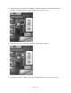
4. Remove the screw from the Aurora circuit board that is adjacent to the JP1 connector and the white serial number/barcode label. Set the screw aside for reuse. 5. Install the standoff post (included with the LT-FW) in this same hole. 6. Grounding yourself to earth ground, remove the LT-FW from its protective static bag.
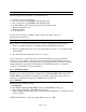
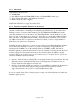
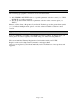
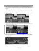
7. Attach the multi-pin connector on the back edge of the LT-FW to the LSlot connector (JP1) on the Aurora main board. When the LT-FW connector pins appear to be lined up correctly with the Aurora LSlot connector, press gently until the connector snaps into place. In some cases, the board may need to be gently flexed for the LSlot connector pins to line up correctly with JP1 on the Aurora main board. Use caution to insure that the pins line up as shown. Incorrect installation could damage the unit. 8.
9. Reinstall the Aurora top cover using the eight screws that had been removed in step 1. Do not over tighten the small screw near the center of the front faceplate as it is easily damaged. 10. Plug in and power up the Aurora using the front panel standby switch. You can see the LT-FW from the slits in the Aurora top cover. If the green LED on the LT-FW lights up, the installation was successful. If the LED does not light, unplug the Aurora and remount the LT-FW, making sure that it is securely attached.
between the host computer and the LT-FW. In order to avoid this, it is CRITICAL that the correct sequence is followed when changing sample rates is necessary. For WDM applications under Windows, the desired sample rate should be selected in the ARC Settings Page prior to changing the sample rate on the master clock source. For ASIO (Windows) and Core Audio (OS X), one should launch the audio project or audio file at the new rate, then change the rate on the master clock source to match.
5. Click “Next >” on the welcome screen 6. Accept the default destination folder for the driver files 7. Click “Next >”from the driver setup screen to start the installation process.
8. At the next screen you’ll be prompted to disconnect and reconnect your devices. At this point connect the appropriate FireWire cable between the Aurora and the FireWire port on your computer. Make sure that the Aurora is powered on. Click “Next >”. 9. You may receive a warning that the driver has not been digitally signed by Microsoft. It is safe to disregard this warning and select “Continue Anyway.” 10. When the installation is finished, you can launch the Aurora Remote Control application.
6 Getting Started With the LT-FW drivers and Aurora Remote Control application installed, the Aurora can now be used with most popular third-party audio applications. However, it is a good practice to verify that the installation was successful and test the Aurora with the following procedure. 6.1 Windows Quick Audio Test The installation of your LT-FW can be tested using the Aurora Remote Control application and the Lynx Demo application included on the Lynx Installation CD.
6. In Lynx Demo, click “File” and navigate to the computer’s Desktop, then select “SineWaveMinus16.wav” and click “Open.” 7. Click “Play.” You should see the progress bar move from left to right. 8. Launch the Aurora Remote Control application. Click the Analog I/O tab. Check for meter activity for Analog Outputs 1&2. If you have speakers or headphones connected to your destination device, you should be hearing audio as well.
6.2 Macintosh Quick Audio Test The installation of your LT-FW can be tested using the Aurora Remote Control application and the Bias Peak demo application included on the Lynx Installation CD. This is a quick way of verifying that the interface is installed correctly and properly connected to your external equipment. 1. Install the Bias Peak demo that is included in the “Demos” folder on the Lynx Installation CD, by clicking on the peakTrial.sit file and following the installation instructions. 2.
7. Click “Hardware Settings…” from the Audio menu. Verify that the LynxLTFW appears as the Output device. Click “OK”. 8. Click “Play” from the Peak transport. You should see meter activity and the counter progressing. 9. Open the Lynx Aurora Remote Control application. Click the Analog I/O tab. Check for meter activity for Analog Outputs 1&2. If you have speakers or headphones connected to your destination device, you should be hearing audio as well.
7 Aurora Remote Control Application Reference The Aurora Remote Control (ARC) application allows control of Aurora parameters from a convenient software interface. It also provides accurate real-time metering for all inputs and outputs, and allows driver parameters such as buffer size and channel mode to be set. The ARC is automatically installed with the Windows driver setup program, and is a separate install under OS X (see Section 5.3, Installing the Driver and Aurora Remote Control Application). 7.
When the Aurora Remote Control application is run via the LT-FW FireWire connection, the Aurora will enter a “lock-out” mode where some front panel controls will be disabled, and control is restricted to the ARC software. The following table details which front panel functions are impacted by “lock out” mode: q SAMPLE RATE This button will not be active. The current operating sample rate will be indicated by the corresponding LED. w SYNC SOURCE This button will not be active.
i IR Transceiver This will function normally. See the Aurora manual for information. o METER This button will function normally. See the Aurora manual for information. a TRIM/AES MODE When the METER select switch is set to “Analog”, this button normally allows the nominal trim level to be set for the analog inputs and outputs. In “Lock Out” mode, this button will not be active, and trims can be set for the Analog inputs and outputs from within the Aurora Remote Control application.
7.3.1 Analog I/O Page This page is viewable by clicking the “Analog I/O” Tab in the top left corner of the Aurora Remote Control application. q These indicators will illuminate when three consecutive full-scale samples are detected on the Aurora Analog Inputs and Outputs or when a summing overrun occurs on the Aurora Analog Outputs. The indicator will remain illuminated for 250ms. w These meters display the instantaneous peak level of audio being sent to the Aurora Analog Inputs and Outputs.
the monitor source for Analog Out 1 while holding down the CTRL key, LSLOT In 1-16 will be assigned to Analog Out 1-16). y These faders allow control over the output level of each monitor source when in Remote Routing mode. This level attenuation occurs in the digital domain, so it is recommended to leave these faders in their default, maximum position in situations where the highest fidelity is required.
to “Remote”. In this state all three LEDs for the TO DIGITAL OUT button on the Aurora front panel will be illuminated. d These buttons allow individual monitor sources to be selected for each digital output when using Remote Routing. Clicking a button allows selection of any Analog, Digital or LSLOT input source. Holding down the CTRL key while selecting a source causes the remaining channels to be set sequentially (i.e.
2) This drop-down menu allows for selection of the signal source that will be routed to the digital outputs. “ANALOG IN”, “AES IN” and “LSLOT In” are global selections, affecting all analog output channels. “LSLOT” routes signals from the computer via the FireWire connection. Choosing “REMOTE” allows individual sources to be assigned from the Monitor Source section of the DIGITAL I/O Page of the Aurora Remote Control application.
7.3.4 About Aurora Remote Control Window This dialog box details the version number of the Aurora Remote Control application, and the hardware revisions, serial numbers and board revisions of the Aurora and LSLOT devices. It also displays the Aurora’s operating temperature and the connection medium being employed. Windows Windows OS X 7.3.5 OS X LT-FW Menu The LT-FW menu provides access to controls for configuring the LT-FW adapter, including buffer size, channel modes, etc.
7.3.6 LT-FW Control Panel (Windows Only) The LT-FW Control panel provides user control over the buffer settings used by the LT-FW, and provides a counter to display if any samples were dropped during ASIO operation. This is a helpful diagnostic tool to determine if an appropriate ASIO buffer size has been selected. For more information about buffer settings, please see Section 8.2.1.1, Controlling Latency by Changing the Buffer Size.
8 Using the LT-FW With the LT-FW drivers and Aurora Remote Control application installed in your computer, you can begin to use the Aurora with most popular third party audio applications. In this section we will explore setting up your Aurora/LT-FW system for your context of use. 8.1 Channel Modes One of the first decisions to be made when setting up the Aurora/LT-FW system is which channel mode to use. Channel modes can be selected from the Aurora Remote Control application LT-FW Menu.
In OS X the M and S distinction are irrelevant. The following four modes are available Mode 1 Maximum Channels 8 2 16 3 16 4 32 Inputs Available 8: Analog 8: Analog 8: Digital 16: Analog 16: Analog 16: Digital Outputs Available 8: Analog 8: Analog 8: Digital 16: Analog 16: Analog 16: Digital For Windows users, there are two different types of modes that change the way the Aurora input and output channels are presented to applications that use MME or DirectSound driver models.
available. For this reason, there will be no difference within ASIO between modes that present the same I/O as multi-channel or stereo devices. For Instance Mode “1M: Analog 1-8 Multichannel” and Mode “1S: Analog 1-8 Stereo” will appear identically within an ASIO application. 8.2 Application Setup The LT-FW was designed to provide maximum compatibility with the most popular audio and multimedia applications that use the Windows MME, DirectSound, ASIO and OS X Core Audio driver standards.
The stream buffer controls the size of audio packets that are used for transfer to the LT-FW hardware. This parameter is important for achieving reliable performance at the buffer size required. A stream buffer size that is ¼ of the ASIO or WDM buffer size is ideal. For instance, when using a 4-millisecond ASIO buffer, it is ideal to use a 1-millisecond stream buffer. Smaller buffer sizes will give you lower latency.
8.2.1.3 Multi-Channel Surround playback When a multi-channel mode has been established for the Aurora (Modes 1M; 2; 3M or 4), then surround-sound material can be played and distributed to multiple outputs on the Aurora. In addition to using an appropriate Channel Mode, the playback software must have an option for decoding and playing back surround-encoded material. The playback software should be set up to use the appropriate Aurora playback device.
When using an ASIO compatible program, the appropriate ASIO device must be selected from a settings or options menu in the application. The correct choice would be “ASIO Lynx Aurora”. Many ASIO applications provide access to an ASIO Control Panel for the device being used. For an LTFW equipped Aurora, this button will launch the LT-FW ASIO Control Panel From this panel, the ASIO Buffer size can be established conveniently within the audio software application, and dropped samples are reported.
8.2.2.2 OS X Audio Applications The Aurora/LT-FW can be used as a playback device for most popular multimedia, home theater and pro audio applications. Some such applications allow selection of specific playback devices. In these cases, an Aurora output device can be selected from the appropriate device selection menu. The way that the Aurora appears as a playback option will depend on the Channel Mode that has been selected in the Aurora Remote Control software.
send and receive signals from the FireWire adapter. LSLOT sources 1-16 on Source B are muted by default. These sources will need to be un-muted in order to pass audio. Any of these monitor sources can be altered to whatever source is desired. It is recommended, however, to keep the LSLOT sources assigned for Source B whenever the Aurora will be used with a computer via FireWire. In addition to Source A and Source B, Analog Outs 1-4 have 16 additional monitor sources available.
When Direct Monitoring is enabled in an application, it can control Sources C through R for analog outputs 1 through 4. These are the monitor sources accessible from the output 1-4 tabs in the ARC Analog Page. Analog outputs 5 and above, and the digital outputs of the Aurora are not accessible via ASIO Direct Monitoring.
Page 37 of 43
9 Troubleshooting Continuous Clicking, popping or crackling noises in your audio: 1. Check clock master settings. In any digital audio configuration, there can be one, and only one master clock. All other digital audio devices must be configured as slaves to the designated master clock. Since the Aurora’s SynchroLock™ technology provides an extremely stable and jitter-resistant clock, we recommend setting the Aurora as the master clock in your digital audio system. 2.
“LSLOT” is selected as the Aurora SYNC SOURCE but SynchroLock will not engage. The SynchroLock status Says “Range” in ARC: When LSLOT is used as a clock source, the computer’s FireWire interface provides the clock signal that the Aurora slaves to. Many FireWire devices output clock signals that are too inaccurate to be used as a reference by the SynchroLock clocking system. For this reason, we recommend selecting “Internal” as the clock source instead of “LSLOT”.
OS X: 1. Check Applications > UltilitiesUtilities > Audio MIDI Setup. Click Configure Speakers > MultiChannel. Choose a surround mode and verify that a different LTFW device output is assigned to each channel. 2. Insure that your media player supports surround sound, and is configured for surround sound operation.
10 Support We are devoted to making your experience with the LT-FW trouble-free and productive. If the troubleshooting and operational sections of this manual did not help resolve your questions, several support options are available to you: 10.1 Lynx Website Support Resources Logging on to http://www.lynxstudio.com/support.
10.4 Return Policy If you have a unit that you suspect is defective or is malfunctioning, contact Lynx technical support via one of the means described above for diagnosis. If the technician determines that the unit is faulty, they will issue an RMA number so you can send the unit in for repair. Units received without a valid RMA number will be refused. All RMA numbers are valid for 30 days from the date of issue. 10.
12 Warranty Information One year Free Labor / One year Parts Exchange This product must be returned to the factory for repair. Who Is Covered? You must have proof of purchase to receive warranty service. A sales receipt or other document showing when and where you purchased the product is considered proof of purchase. This warranty is enforceable only by the original retail purchaser.