Owner´s manual Millenium ADC Analog/Digital Converter
Table of Contents Unpacking the Millennium ADC 4 Operating Voltage 4 Serial Number Registration 4 Introduction 5 Accessories 6 Front Panel 7 Rear Panel 8 Remote Control 9 Setup Cartr.: 1 - Load Preset - DSP Cart. Filter - 50 kHz Zero - Cartridge Gain - Cartr. Balance - Cartr. Capacit. - Cartr.
Unpacking the Millennium ADC Carefully remove the unit and accessory kit from the carton, visually check for shipping damage. Contact both the shipper and your Lyngdorf Audio dealer immediately if the unit bears any sign of damage from mishandling. All Lyngdorf Audio equipment is carefully inspected before leaving our factory. Keep shipping carton and packing material for future use or in the unlikely event that the unit needs servicing.
Introduction Congratulations on your investment in the Lyngdorf Audio Millennium ADC (Analog to Digital Converter). The Lyngdorf Audio Millennium ADC is a high-performance 2-channel Analog to Digital Converter with 4 line inputs. Using a combination of state-of-the-art analog circuitry and Digital Signal Processing to support the two balanced 24 bit converters per channel, the Millennium ADC sets new performance standards for analog to digital conversion.
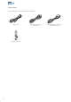
Accessories You should find the following accessories included: Mains cord 1 2 4 5 7 8 9 digital 0 info 3 6 menu analog AMP RCS CD channel TUNER volume ENTER A/B random repeat Remote control 6 Millennium Link cable (5 pin XLR) RS-232 cable for firmware upgrade from a PC
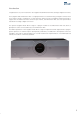
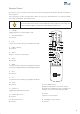
Front Panel 1 2 3 4 5 6 Figure 1: Millennium ADC front panel. The buttons/controls on the front panel of the TDAI 2200 can all be operated either with direct presses or by operating the corresponding keys on the supplied remote control. All the keys on the front panel [except the Mains switch (1)] are duplicated on the remote control as well. 1. Mains switch Turns the power to the Millennium ADC on or off. 2. Left control button.
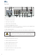
Rear Panel 2 1 3 5 4 PHONO GROUND Millennium ADC Phono Stage L R 6 7 8 9 10 11 12 13 Figure 2: Millennium ADC rear panel. 1. Binding post for phono ground. 2. Optional phono stage module. 3. Millennium ADC serial number label. 4. RS-232 AUX and INPUT RJ45 connectors. The RS-232 communication connectors are for connection to a computer for firmware upgrade. Please visit www.lyngdorf.com for instructions and available firmware. 5. Mains voltage input selector.
Remote Control The remote control is used to access the menu system and replicate the buttons directly accessible on the front panel. The four buttons used for selecting which device to control are described below. To control the Millennium ADC the AMP key should be pressed. The functionality of the remote control depends on the products in your set-up. The below description applies to operation of the Millennium ADC only. 1. Standby Toggles between on and stand-by mode. 2. Numerical buttons No function.
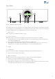
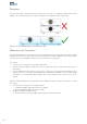
Placement The Millennium ADC should be placed well away from any source of magnetic fields like wall mains adapters. Also avoid placing on top of a power amplifier – instead place them ‘side by side’. Figure 3. Recommended placing of the Millennium ADC.
Menu Tree Common Menus Main Menu ADC Input Related Menus Input Related Menus Dig. Samplerate Comm. Address Comm. Speed Display Timeout Remote Control Factory Reset Phono Input Menus Main Menu ADC Common Menus High Pass Filter De-emphasis Select Cartridge Setup Cartr. : 1 Polarity Exit Main Menu Phono Cartridge: 1 Load Preset DSP Cart . Filter 50 kHz Zero Cartridge Gain Cartr. Balance Cartr. Capacit . Cartr. Impedance Exit Cartr.
Menu Operation In the following the general menu operation is described with Display Timeout menu (used as an example only). The menus available depend on the selected input. All settings outside the common menus apply to the selected input only. Please refer to the menu tree. When The Millennium ADC is switched on select the menu by pressing and holding the right control button until the menu appears or press Menu on the remote control.
Common Menus Digital Sample Rate Available sample rates are 48, 96 and 192 kHz. Choice of sample rate depends on the compatibility with the actual amplifier. If your amplifier accepts all sample rates, we recommend you to test the different settings to find your personal preference.
Phono Input Menus High Pass Filter The high pass filter can be chosen to filter away rumble and/or acoustic feedback. Available settings are 10, 15 or 20 Hz. This is referred to as the F2 point in fig. 4. De-emphasis Records made before 1955 were recorded with different emphasis curves, requiring different de-emphasis during playback. Some records specify the emphasis curve used on their cover, but in many cases you have to make an educated guess based on record label and year of release.
Setup Cartr.: 1 Load Preset If you use one of the pre-loaded cartridges you can load this directly which then automatically sets up the ADC to this cartridge (gain, capacitance, impedance and DSP cartridge filter). If you have a different cartridge, you need to make these settings manually. If you at a later stage wish to de-select a pre-loaded cartridge, simply select ‘Default’ in this menu to set this cartridge back to the factory default settings. DSP Cart.
Input sensitivity versus cartridge output specification The output voltage of cartridges are generally specified at a stylus velocity of 5 cm/sec. High performance turntable/tone arm/cartridge combinations can track up to 50-75 cm/sec resulting in an output of 10 to 15 times the output voltage specified for the cartridge. The input sensitivity specified for the Millennium ADC is the voltage required for full-scale output. In the guide (fig 5) we have calculated the settings with a track ability of 50cm/sec.
Cartr. Balance The Cartridge Balance adjustment enables you to compensate for differences between left and right channel. The balance is adjusted by decreasing the left or right channel between 0 - 3dB. Cartr. Capacit. The cartridge capacitance can be set to 100 or 430pF. Pls. refer to the specification of your cartridge to find the correct setting. For MM cartridges start with 100pF. If this setting sounds too ‘bright’, use 430pF. For MC cartridges use 430pF unless otherwise specified. Cartr.
Analog Input 1- 4 Menus Input Gain The Input Gain enables you to match levels from different sources as well as obtaining full scale output on your amplifier. The Input Gain can be adjusted up to +18dB in 0.1 dB steps. Please refer to the output level specifications of the source and then use the table in fig. 6 as a guide when adjusting relative input gain. Setting the Input Gain too high will result in distortion. Use the table below as a guide but always use your ears when setting the Input Gain.
Technical Specifications Analog inputs Parameter Value Note Balanced input connectors 3 pin XLR female, gold plated Case=Gnd, Pin1=Gnd, Pin2=Hot(+), Pin3=Cold(-) Balanced input CMRR -40dB 20 Hz-20 KHz. Unbalanced input connectors RCA (phono) jack, gold-plated. Case=Gnd, Tip=Hot(+) Input impedance 10K Ohm Input sensitivity 550mV to 4.4V L/R crosstalk, 20 Hz-20 KHz -111dB For full-scale output. Frequency linearity L/R, 20 -20k ±0.
Digital outputs Parameter Value Note Balanced output connector 3 pin XLR male, gold-plated Case=Gnd, Pin1=Gnd, Pin2=Hot(+), Pin3=Cold(-) Balanced output impedance 110 ohms Transformer isolated output. Balanced output voltage 1.7Vpp With 110 Ohm load. Balanced output jitter 350pS With 110 Ohm load Unbalanced output connector RCA (phono) jack, gold-plated. Case=Gnd, Tip=Hot(+) Unbalanced output impedance 75 ohms Transformer isolated output. Unbalanced output voltage 0.
www.lyngdorf.