
User's Manual

Lecip Arcontia confidential (V1.00 2019-05-13)
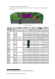
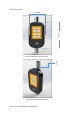
5. Electrical Interface Overview
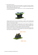
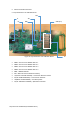
5.1 Top Placement of LV-700 Main Board
SD1
J1 J10
J6 SIM SAM (1-4)
Figure 10: Top Placement of LV-700 Main Board J9
• SAM1 – Secure Access Module Slot no 1
• SAM2 – Secure Access Module Slot no 2
• SAM3 – Secure Access Module Slot no 3
• SAM4 – Secure Access Module Slot no 4
• SIM1 – SIM Module Slot
• SD1 – Micro SD slot for additional memory
• J1 (Hirose: FX23-40P-0.5SV20) – Connection Board Connector
• J6 (FCI: SFV8R-3STBE1HLF) – Touch Screen Interface
• J10(Wurth: 614105150621) – For MCU Update
• J9 (FCI: 10051922-1210EHLF) – QR Camera Interface