
Installation & Assembly

www.allstarlighting.com
2
33 Randolph Ave. • Avenel NJ 07001 | 732-882-1500
INSTALLATION GUIDE
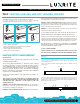
FIG. 5
THE WIRING OF MULTIPLE LAMPS IS THE SAME AS ABOVE.
T8 LED Tube
L N
STEP 5: Check the lampholders. If the lampholders ar shunted, go to Step 6.
If the lampholders are not shunted, go to Step 7. For “One End” wiring configu-
ration only, “WARNING: To avoide potential fire or shock hazard, do not use
this retrofit kit in luminaires employing shunted bi-pin lampholders. Note:
Shunted lamp holders are found only in fluorescent luminaires with
Instant-Start ballasts. Instant-start ballasts can be identified by the words
”Instant Start” or “I.S” marked on the ballast. This designation may be in the
form of a statement pertaining to the ballast itself, or may be combined with
the marking for the lamps with which the ballast is intended to be used, for
example F40T12/IS. For more information, contact the LED luminaire retrofit
kit manufacturer.”
STEP 6: If the lamp holders are shunted, connect one lead from each
lampholder to branch circuit as follows, “Leads 3 and 4” connected to L;
“Leads 1 and 2” connected to N as shown in Fig. 3.
STEP 7: The lampholders are not shunted. “One End” or “Both End” wiring
can be selected. For “One End” wiring, connect one lead from each lamphold-
er to branch circuit as follows, “Leads 1” connected to L; “Leads 2” connected
to N. Don’t connect Lead 3, Lead 4 to the circuit as shown in Fig. 4. Note: Leads
1 and Leads 2 are respectively connected to L and N1 on the LED tube, don’t
connect N2 and N3 in the circuit.
For “Both Ends” wiring, Connect one lead from each lampholder to branch
circuit as follows, “Leads 1 and Leads 2” connected to L; “Leads 3 and Leads 4”
connected to N as shown in Fig. 4A
FIG. 3
Lampholder
N L
Lampholder
1
2
N
N
4
3
L
L
BALLAST
FIG. 6
Lampholder
N L
Starter
Lampholder
1
2
4
3
BALLAST
FIG. 4
Lampholder
N L
Lampholder
1
2
Connect to
branch circuit L
Don’t connect
to branch circuit
Don’t connect
to branch circuit
Connect to
branch circuit N
4
3
BALLAST
FIG. 4A
Lampholder
N L
Lampholder
1
2
3
4
Connect to
branch circuit L
Connect to
branch circuit N
BALLAST
L
N1
N2
N3
STEP 8: Attach the field applied label to the luminaire. Install ballast cover
and diffuser (if applicable) back on Luminaire, and T8 LED tube as shown in
Fig. 5
STEP 9: Turn on the AC power source, LED Tube will light.
THE WIRING OF MULTIPLE LAMPS IS THE SAME AS ABOVE.
REPEAT STEPS 8 AND 9
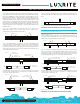
RETROFIT FLUORESCENT LUMINAIRE WITH SEPARATE
STARTER AND MAGNETIC BALLAST
REPEAT STEPS 1 TO 3
STEP 4: Original circuit as shown in Fig. 6. Cut lampholder leads “1,2,3,4”, cut
as far away from the lampholders to allow for longer lengths of wire at both
lampholders. Note: Ballast must be retained in place.
STEP 5: “One End” or “Both End” wiring can be selected. For “One End” wiring,
connect one lead from each lampholder to branch circuit as follows, “Leads 1”
connected to L; “Leads 2” connected to N. Don’t connect Lead 3, Lead 4 to the
circuit as shown in Fig. 7. Note: Leads 1 and Leads 2 are respectively connected
to L and N1 on the LED Tube, Don’t connect N2 and N3 in the circuit.
For “Both Ends” wiring, Connect one lead from each lampholder to branch
circuit as follows, “Leads 1 and Leads 2” connected to L; “Leads 3 and Leads 4”
connected to N as shown in Fig. 7A
FIG. 7
Lampholder
N L
Starter
Lampholder
1
2
4
3
BALLAST
Connect to branch circuit L
Connect to branch circuit N
Don’t connect
to branch circuit
Don’t connect
to branch circuit
N2
N3
L
N1
FIG. 7A
Lampholder
N L
Starter
Lampholder
1
2
4
3
BALLAST
Connect to
branch circuit L
Connect to
branch circuit N
L
N
L
N