
Installation Guide

1
Pre-Installation
1. Determine the number of controls to be ganged in the same
wallbox. Allow the space equivalent of a full wallbox for EVERY
control to be installed.
2. If more than one control is being ganged in the same
wallbox, side sections must be removed for proper fit. When
controlling magnetic ballasts, breaking side sections off the
control will reduce the maximum number of lamps per control.
Use the following charts to determine the maximum capacity of
each control.
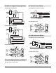
3. Remove desired inner side sections. Using pliers, bend side
sections down as far as you can and then back to their original
position. See diagrams below. Side sections will break off. Do
not remove outer side sections of controls on the ends of the
installation.
These products are covered under one or more of the following U.S. patents:
4,835,343; 4,835,816; 5,180,886 and corresponding foreign patents. U.S. and
Foreign patents pending. Lutron, Claro, and Skylark are registered trademarks of
Lutron Electronics Co., Inc.
2002 Lutron Electronics Co., Inc.
Installation Instructions
Please Leave for Occupant
Fluorescent Dimmers
SF-10P, SF-103P
120VAC, 60Hz
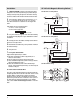
Package Contents and Part Identification
Mounting Hole
Slider
Low-end
Adjustment
Thumbwheel
On/Off
Rocker
Switch
Side
Section
Breakoffs
2 Mounting Screws
6 Wire
Connectors
(SF-103P)
5 Wire
Connectors
(SF-10P)
Important Notes
Please Read Before Installation
Wallbox and Location: A single-gang wallbox (3" high x 2" wide
x 2
1
/2" deep) will service all individual Skylark dimmers. These
dimmers are designed to operate in ambient temperatures from
0
o
C (32
o
F) to 40
o
C (104
o
F). Allow a minimum space of 4
1
/2"
above and below the dimmer for proper heat dissipation.
Short Circuit Check: Check new installation for short circuits
prior to installation of dimmer by connecting incoming hot wire to
ballast input wires with POWER OFF. Magnetic ballast:
Connect the black and brown or black and yellow/blue wires
together. Electronic ballast: Connect the black and orange
wires together. Turn power on. If lights do not work, or breaker
trips, a short is present. Correct the wiring and check circuit
again. Install dimmer only when short is no longer present. This
check should be done by a qualified electrician.
Sockets: For magnetic ballasts, use lamp disconnect sockets
only. This meets U.L. and NEC regulations and maintains
personal safety standards. For electronic ballasts, knife edge
sockets are recommended.
Lamps: Energy Saver Lamps may NOT be used with this
dimmer. With magnetic ballasts only, do not mix different wattage
lamps in the same circuit. NOTE: To ensure proper dimming
performance and full lamp life, fluorescent lamps should be
operated at full intensity for 100 hours prior to dimming.
Magnetic ballasts: Use ONLY dimming ballasts shown on chart
in step 2 of Pre-Installation. Do not mix 1 and 2 lamp ballasts in
any one dimmer circuit. Do not mix ballast manufactured by more
than one company. Using single lamp ballasts will produce the
most consistent low end dimming level.
Multi-phase Applications (120/208-3 Phase): In multi-phase
applications use a separate neutral for each phase containing a
dimmer. Contact the
Lutron Technical Support Center
toll-free
for Application Note #17, "Common Neutral Interaction".
Magnetic Ballasts: Maximum number of lamps per
control
Electronic Side Sections Removed
Ballasts None One Two
Lutron
FBD- Series 8 amps 8 amps 8 amps
ECO- Series 8 amps 8 amps 8 amps
Electronic Ballasts: Maximum current per control
Magnetic Side Sections Removed
Ballasts None One Two
Universal
550LTCP
†
10 lamps 8 lamps 6 lamps
502ATCP
†
* 10 lamps 8 lamps 6 lamps
Advance
DIM 140H 8 lamps 6 lamps 4 lamps
DIM 240H* 8 lamps 6 lamps 4 lamps
Valmont
8G5001W 10 lamps 8 lamps 6 lamps
8G5007W* 10 lamps 8 lamps 6 lamps
†
can be used with 30W lamps
* 2 lamp ballast
No Side
Sections
Removed
One Side
Section
Removed
Middle Unit Has
Two Side Sections
Removed